Method for analyzing ultimate strength of ultra-large floating body structure under action of complex loads
A complex load and ultimate strength technology, applied in the direction of instruments, design optimization/simulation, electrical digital data processing, etc., can solve problems such as insecurity and inaccurate ultimate strength evaluation, and achieve convenient operation, good industrial application prospects, and wide application range wide effect
- Summary
- Abstract
- Description
- Claims
- Application Information
AI Technical Summary
Problems solved by technology
Method used
Image
Examples
Embodiment 1
[0095] Embodiment 1: The ultimate strength analysis of the horizontal brace in the super-large floating body is taken as an example for illustration.
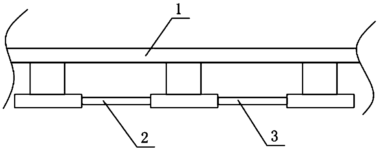
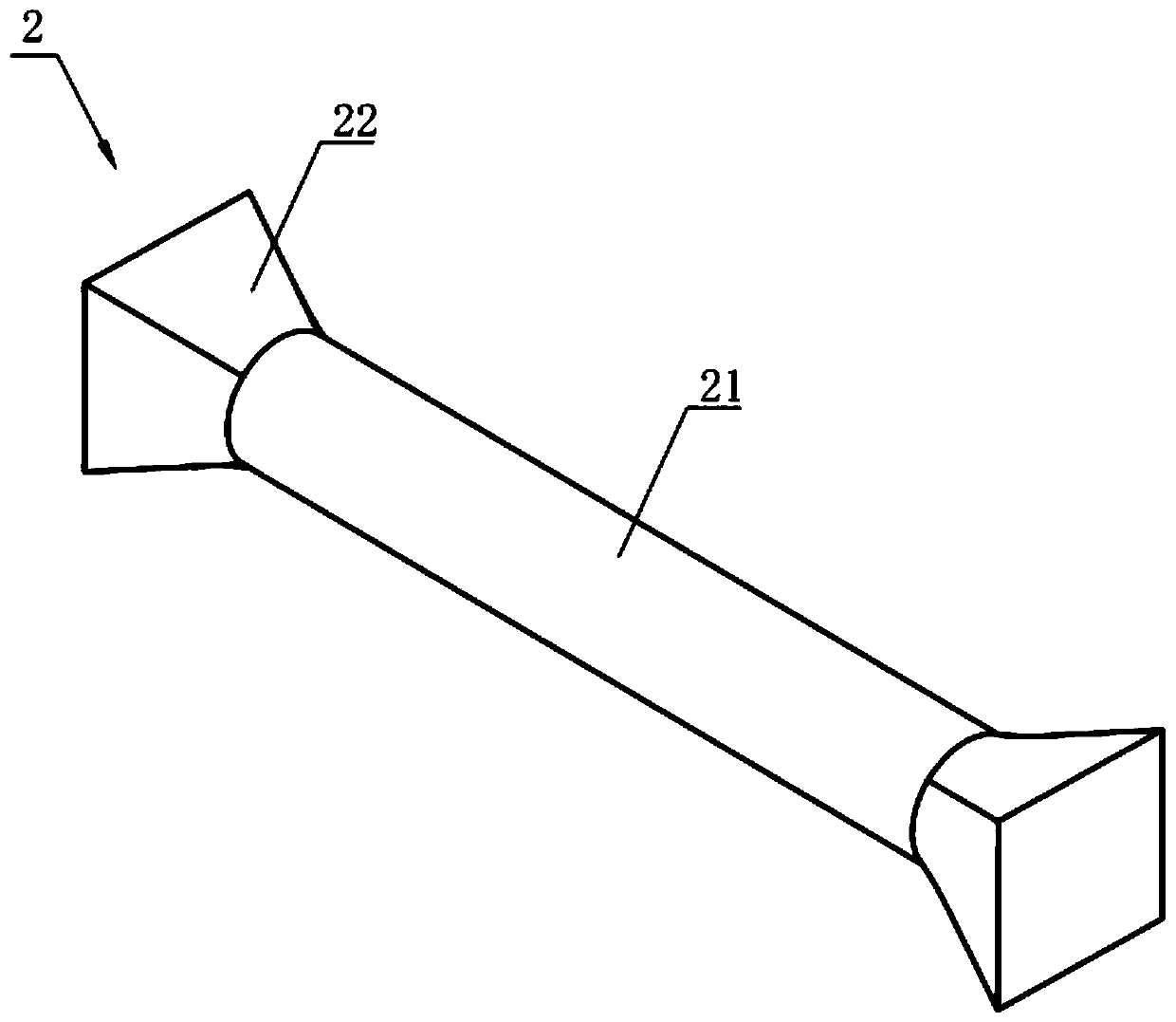
[0096] Such as figure 2 and image 3 As shown, the cross brace 2 includes a cylindrical part 21 in the middle, and the two ends of the cylindrical part 21 are respectively extended with supporting parts 22, and the two supporting parts 22 are fixedly connected with the super large floating body 1 respectively; Figure 4 As shown, a plurality of reinforcing ribs are arranged inside the cylindrical portion 21 .
[0097] Establish the finite element model of the cross brace 2, and divide the grid units, such as Figure 4 shown;
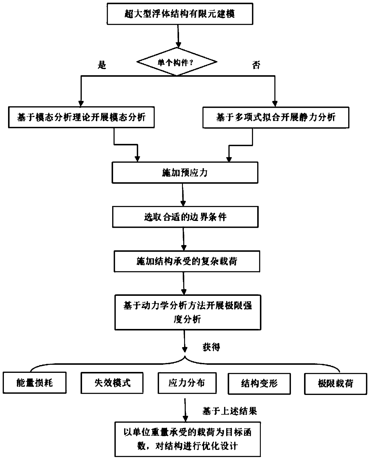
[0098] Brace 2 is a super-large floating body structure composed of a single component. Therefore, based on modal analysis, the first-order mode of brace 2 is obtained. Through static analysis, the node displacement of each unit is obtained, and the node displacement with the largest magnitude is comp...
Embodiment 2
[0106] Embodiment 2: The ultimate strength analysis of the main structure in the super-large floating body is taken as an example for illustration.
[0107] Such as Figure 12 As shown, the main structure is a rectangular frame structure as a whole, including a deck frame 31 at the top, a floor frame 33 at the bottom, and a side frame 32 connecting the deck frame 31 and the bottom frame 33 on both sides. Vertical longitudinal bulkhead 34 and multiple transverse bulkheads 35, such as Figure 13 As shown, a plurality of reinforcing ribs 36 are arranged inside the main structure; wherein the floor frame 33 is fixedly connected to the super-large floating body 1, and the two ends of the main structure are connected with connectors.
[0108] Establish the finite element model of the main structure and divide the grid units, such as Figure 14 shown;
[0109]The main structure is composed of multiple components, so the polynomial fitting analysis is used to obtain its first-order...
PUM
 Abstract
Description
Claims
Application Information
 - R&D
- Intellectual Property
- Life Sciences
- Materials
- Tech Scout
- Unparalleled Data Quality
- Higher Quality Content
- 60% Fewer Hallucinations
Browse by: Latest US Patents, China's latest patents, Technical Efficacy Thesaurus, Application Domain, Technology Topic, Popular Technical Reports.
© 2025 PatSnap. All rights reserved.Legal|Privacy policy|Modern Slavery Act Transparency Statement|Sitemap|About US| Contact US: help@patsnap.com


