Supercharge Your Innovation With Domain-Expert AI Agents!

A corner disinfection device for hygiene management

A technology for disinfection equipment and corners, applied in sanitary equipment, disinfection, construction and other directions for toilets, which can solve problems such as inability to disinfect dead corners.

Inactive Publication Date: 2021-01-29
徐嘉
View PDF6 Cites 0 Cited by
  • Summary
  • Abstract
  • Description
  • Claims
  • Application Information

AI Technical Summary

Problems solved by technology

[0006] In order to overcome the disadvantage that the current disinfection equipment cannot disinfect the dead corners, the purpose of the present invention is to provide a corner disinfection equipment with a wide application range and which can disinfect the dead corners. This is the technical problem to be solved by the present invention

Method used


Image

  • A corner disinfection device for hygiene management
  • A corner disinfection device for hygiene management

Examples


Embodiment 1

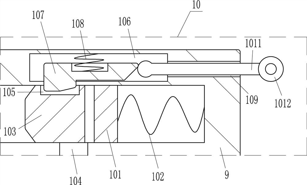
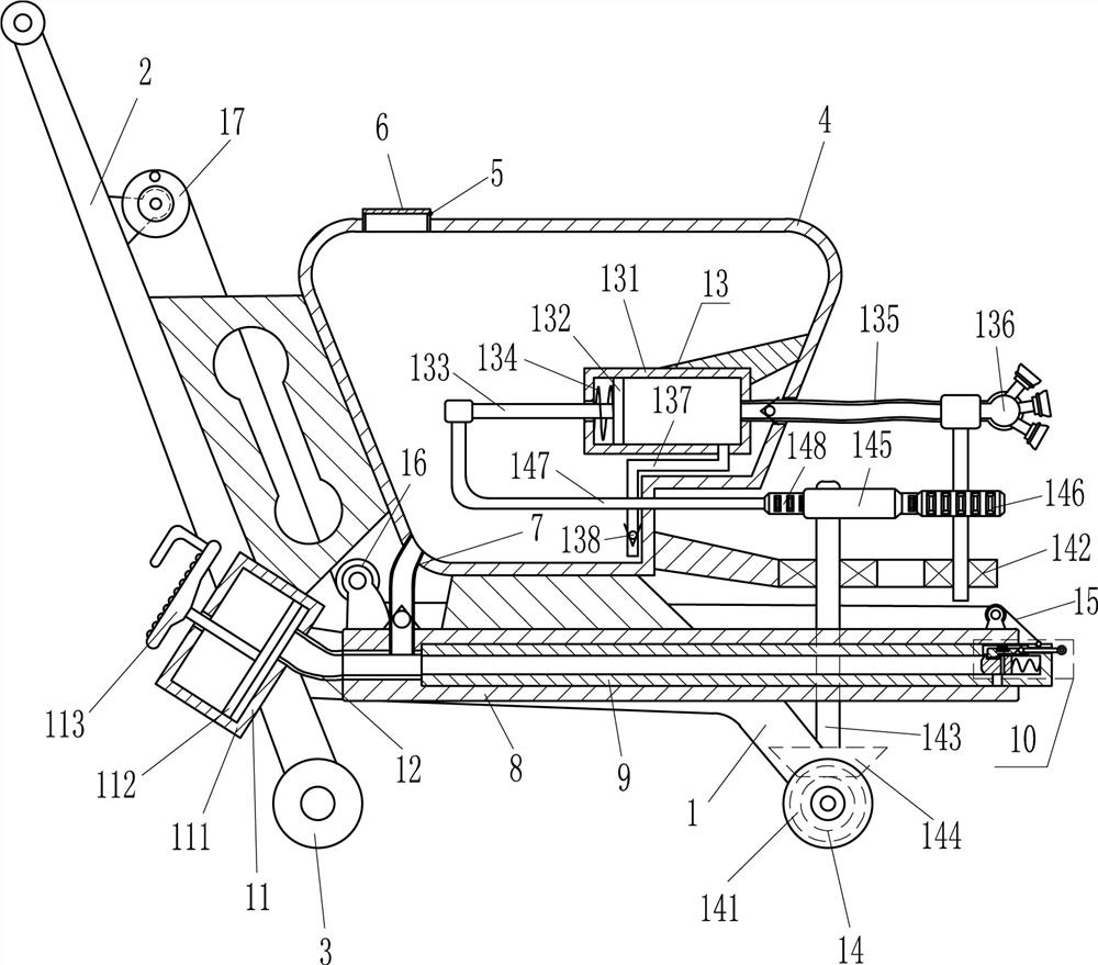
[0019] as attached figure 1 to attach figure 2 As shown, a corner disinfection equipment for sanitation management includes a mounting plate 1, a first push rod 2, wheels 3, a liquid storage tank 4, a liquid inlet pipe 5, a cover plate 6, a liquid outlet pipe 7, and a hollow sleeve 8 , hollow pipe 9, sprinkler 10, power unit 11, first hose 12, liquid sprinkler 13 and transmission device 14, first push rod 2 is installed on the left side of the top of the mounting plate 1, and wheels 3 are installed on the bottom of the mounting plate 1 , the top of the mounting plate 1 is equipped with a liquid storage tank 4, the top of the liquid storage tank 4 is provided with a liquid inlet pipe 5 with a cover plate 6, and the left side of the bottom of the liquid storage tank 4 is connected with a liquid outlet pipe 7 with a one-way valve, A hollow sleeve 8 is installed in the middle of the mounting plate 1, and a hollow tube 9 is slidingly provided in the hollow sleeve 8. The tail end ...

Embodiment 2

[0026] as attached figure 1 As shown, the power unit 11 includes a first cylinder 111, a first piston 112 and a pedal 113, the first cylinder 111 is installed on the lower part of the first push rod 2, and the first push rod 2 is connected to the first push rod 2 by bolts. A cylinder body 111 is connected, the first cylinder body 111 is slidingly provided with a first piston 112, the first piston 112 is connected with a foot pedal 113 for stepping on, and the first piston 112 is connected to the foot pedal 113 by bolts. Connected, the pedal 113 is located outside the first cylinder 111 .

[0027] Working principle: When disinfecting corners, the operator first steps on the pedal 113 upwards, thereby driving the first piston 112 to slide upwards in the first cylinder 111, and pumps the disinfectant in the liquid storage tank 4 into the first soft cylinder. tube 12, and then step down on the pedal 113 to press the gas in the first cylinder 111 into the hollow sleeve 8, push the...

Embodiment 3

[0031] as attached figure 1 Shown, also comprise backguy 15, fixed pulley 16 and reel 17, hollow tube 9 top right sides are connected with backguy 15, hollow casing 8 top left and right sides all are equipped with fixed pulley 16, hollow casing 8 passes bolt The connection mode is connected with the fixed pulley 16, the first push rod 2 is equipped with a reel 17 with a handle, and the backguy 15 is connected with the reel 17 around two fixed pulleys 16.

[0032] Working principle: when the hollow tube 9 is pushed to move to the right, the winding wheel 17 will automatically release the wire. After the corner is sterilized, the operator turns the winding wheel 17 to collect the pull wire 15, and pulls the hollow tube 9 to move to the left to reset. In this way, the hollow tube 9 can be reset more conveniently.


PUM


Abstract

The invention relates to disinfecting equipment, in particular to corner disinfecting equipment for conservancy of sanitation. In order to solve the technical problem, the invention provides the corner disinfecting equipment for conservancy of sanitation, which is wide in application range and can perform disinfecting on hygienic dead angles. The technical scheme of the corner disinfecting equipment for conservancy of sanitation is characterized by comprising a mounting plate, a first push rod, and wheels, wherein the first push rod is mounted on the left side of the top of the mounting plate.According to the corner disinfecting equipment for conservancy of sanitation disclosed by the invention, a spraying device is driven by a power device to enter a corner, so that the dead angle can bedisinfected; the power device can transmit power to a liquid spraying device, drive a second cylinder to suck in and spray out disinfectant liquid, and can also drive a nozzle to rotate, so that themedicine spraying range of the nozzle can be enlarged; when a hollow pipe moves rightwards, a wire winding wheel can perform wire releasing automatically; and after disinfecting is performed on the corner, an operator rotates the wire winding wheel to retract a pull wire and pull the hollow pipe to move leftwards for restoration, so that the hollow pipe can be more convenient to restore.

Description

technical field [0001] The invention relates to a disinfection device, in particular to a corner disinfection device for hygienic management. Background technique [0002] Disinfection refers to the method of killing pathogenic microorganisms, but not necessarily bacterial spores. Chemical methods are usually used to achieve the effect of disinfection. Chemicals used for disinfection are called disinfectants. In people's daily life, viruses are ubiquitous, and people may be infected with viruses if they are not careful, especially bacteria are most likely to breed near garbage dumps and dead corners. [0003] At present, when disinfecting, it is generally used to disinfect the place where bacteria are easy to breed through a disinfection machine. This disinfection method has the following disadvantages: the use of an insecticide machine for disinfection requires people to carry it on their backs, and multiple equipment requires multiple workers. The operation makes the la...

Claims


Application Information

Patent Timeline
Patent Type & Authority Patents(China)
IPC IPC(8): A61L2/18A61L2/26
CPCA61L2/18A61L2/26A61L2202/16A61L2202/25
Inventor 徐嘉褚云英靳永峰张磊吕伟建
Owner 徐嘉
Features
  • R&D
  • Intellectual Property
  • Life Sciences
  • Materials
  • Tech Scout
  • Unparalleled Data Quality
  • Higher Quality Content
  • 60% Fewer Hallucinations
Learn More