Tunnel type welding machine capable of being directly changed and welding method thereof

A tunnel-type, direct technology, applied in the direction of welding equipment, welding equipment, auxiliary welding equipment, etc., can solve the problems of high cost, low efficiency, low precision, etc., and achieve the effect of reducing cost, high operating efficiency and reducing manual operation

Pending Publication Date: 2020-02-04
GUANGDONG YI HENG IND EQUIP CO LTD
View PDF9 Cites 0 Cited by
  • Summary
  • Abstract
  • Description
  • Claims
  • Application Information

AI Technical Summary

Problems solved by technology

[0002] Hollow cylinder structural parts such as water storage water heater liner, gas storage tank, etc. are rolled into a cylinder shape by metal sheets, and then welded by welding equipment. Some existing automatic welding equipment can complete the corresponding welding process , in order to reduce the inefficiency, high cost, low precision and other deficiencies that were prone to occur in the previous production process, but these welding equipment need to be adjusted according to the size of the cylinder to be welded before the welding operation or before loading the workpiece. Therefore, it is necessary to adjust or change the workpiece positioning fixture of the welding equipment, or even select or replace the corresponding applicable positioning mold, and then correct various parameters to match the workpiece, and at the same time make the corresponding welding part of the workpiece correspond to the welding equipment Therefore, it is necessary to repeat the above cumbersome operations every time the size of the cylinder to be processed by the welding equipment is changed or changed. Therefore, even if the welding equipment can fully automate the welding process, it still takes considerable manpower and time to adapt the workpiece. , these welding equipment still have considerable inconvenience in practical application

Method used


Image

  • Tunnel type welding machine capable of being directly changed and welding method thereof
  • Tunnel type welding machine capable of being directly changed and welding method thereof
  • Tunnel type welding machine capable of being directly changed and welding method thereof

Examples


Embodiment Construction

[0023] Embodiments of the present invention are described in detail below, examples of which are shown in the drawings, wherein the same or similar reference numerals designate the same or similar elements or elements having the same or similar functions throughout. The embodiments described below by referring to the figures are exemplary and are intended to explain the present invention and should not be construed as limiting the present invention.

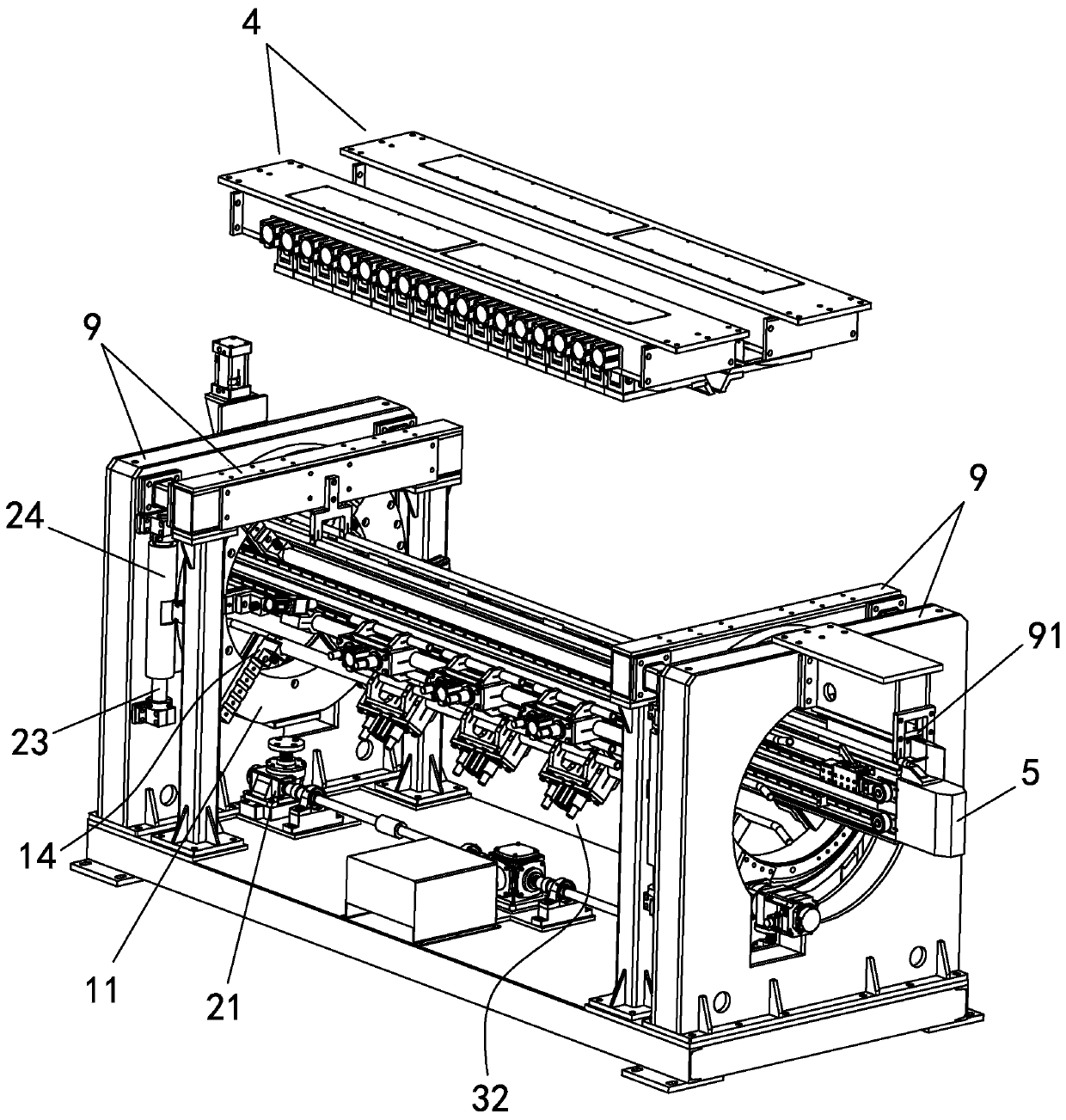
[0024] refer to figure 1 , the directly changeable tunnel type welding machine of the present invention includes a welding pressing mechanism 4, a welding support assembly 5 and a positioning mechanism, and the positioning mechanism includes a positioning device, a positioning device and a pressing device; the positioning device has two and The front and back correspond to each other. The positioning device has several centering and adjustable limit points distributed around the center. The two positioning devices can adjust the ...


PUM


Abstract

The invention discloses a tunnel type welding machine capable of being directly changed and a welding method thereof. The tunnel type welding machine comprises a welding and compressing mechanism, a welding and bearing assembly and a positioning mechanism, and the positioning mechanism comprises two positioning devices, a transposition device and a pressure position device; the two positioning devices correspond to each other and are provided with a plurality of limiting points with centering distributed in a surrounding mode and being capable of being positioned; the pressure position deviceis located between the two positioning devices, the pressure position device is correspondingly connected with the corresponding limiting points on the two positioning devices, the pressure position device can move with the limiting points in a transposition mode and is provided with at least two pressure welding positions, and the pressure welding positions are distributed around center shafts ofthe positioning devices; the transposition device can synchronously and conformably drive the two positioning devices to rise, lift and shift; the welding and bearing assembly penetrates through thelimiting points of the two positioning devices in a suspending mode; and the welding and compressing mechanism is located above the welding and bearing assembly. According to the tunnel type welding machine capable of being directly changed and the welding method thereof, workpieces with different sizes can be subjected to welding and machining correspondingly, the efficiency and precision are high, and the cost can be effectively reduced.

Description

technical field [0001] The invention relates to welding equipment, in particular to a directly changeable tunnel type welding machine and a welding method thereof. Background technique [0002] Hollow cylinder structural parts such as water storage water heater liner, gas storage tank, etc. are rolled into a cylinder shape by metal sheets, and then welded by welding equipment. Some existing automatic welding equipment can complete the corresponding welding process , in order to reduce the inefficiency, high cost, low precision and other deficiencies that were prone to occur in the previous production process, but these welding equipment need to be adjusted according to the size of the cylinder to be welded before the welding operation or before loading the workpiece. Therefore, it is necessary to adjust or change the workpiece positioning fixture of the welding equipment, or even select or replace the corresponding applicable positioning mold, and then correct various parame...

Claims


Application Information

Patent Timeline
Patent Type & Authority Applications(China)
IPC IPC(8): B23K31/02B23K37/00B23K37/04B23K37/02B23K101/12
CPCB23K31/02B23K37/00B23K37/0443B23K37/0211B23K2101/12
Inventor 邱海涛曹华平文敬春李建琳陈大为胡健生
Owner GUANGDONG YI HENG IND EQUIP CO LTD
Why Eureka
Try Eureka