Manipulator to control clamping deformation

A manipulator and gripper arm technology, applied in the field of manipulators that control gripping deformation

Active Publication Date: 2021-04-16
ZHEJIANG UNIV
View PDF5 Cites 0 Cited by
  • Summary
  • Abstract
  • Description
  • Claims
  • Application Information

AI Technical Summary

Problems solved by technology

However, so far, there is a lack of manipulators with this capability

Method used


Image

  • Manipulator to control clamping deformation
  • Manipulator to control clamping deformation
  • Manipulator to control clamping deformation

Examples


Embodiment Construction

[0082] Below in conjunction with accompanying drawing this design is described further.

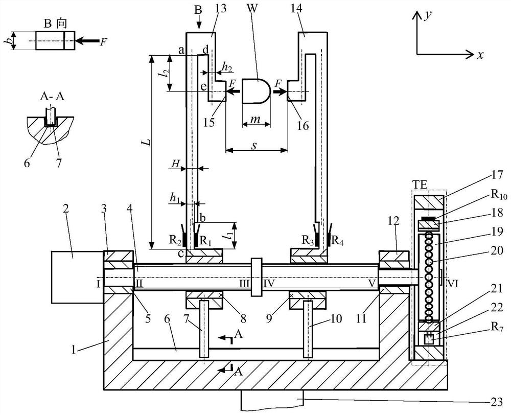
[0083] refer to Figure 1-Figure 6 , this design is a manipulator to control clamping deformation. The manipulator is composed of a frame 1, an encoding screw, a driver 2, a gripper and a numerical control.

[0084] The structure of the frame 1 includes a rectangular base plate, a shaft coupling 23 located below the base plate for connecting the robot arm, a left bearing support plate 3 located on the left side above the base plate, a right bearing support plate 12 located on the right side above the base plate, and a The U-shaped guide limit groove 6 on the upper surface. The left bearing support plate 3 is embedded with the left bearing 5, and the right bearing support plate 12 is embedded with the right bearing 11. The two bearings are in a coaxial position, and the axis is parallel to the axis of the U-shaped guide limit groove 6.

[0085] The coding screw consists of a micrometer ...


PUM


Abstract

The invention discloses a manipulator for controlling clamping deformation, which is used for a robot. The device consists of a frame, an encoding screw, a holder, a driver and a numerical control. The coding screw consists of a micrometer screw and a three-state encoder, and the three-state encoder includes a toothed disc and four pairs of cantilever beam sensors. The gripper includes two gripping arms. The coding screw and the holder form a force-deformation-displacement composite sensing mechanism, which is installed on the frame and connected with the driver. When the device is working, the CNC controls the rotation of the driver and the coding screw, the gripper clamps the object, and the composite sensing mechanism interacts with the CNC to transmit measurement and control signals to measure the clamping force and the distance between clamping points in real time to control the deformation of the object.

Description

technical field [0001] This design is a manipulator that controls clamping deformation and is used in industrial robots. Background technique [0002] The manipulator is the front-end operating mechanism of a variety of robots including a large number of automated production, processing, and testing equipment in the industrial field. Its basic function is to pick and place, that is, to grab, transfer, and release objects. During the pick-and-place process, it is necessary to control the clamping force of the manipulator on the object. For many applications, it is also necessary to control the deformation of the object caused by the clamping force with sufficient control accuracy. So far, however, there is a lack of manipulators with this capability. Contents of the invention [0003] The purpose of this design is to provide a manipulator for controlling clamping deformation for industrial robots. The manipulator clamps the object in a flexible manner, and realizes the m...

Claims


Application Information

Patent Timeline
Patent Type & Authority Patents(China)
IPC IPC(8): B25J15/02B25J15/12B25J9/16B25J13/08
CPCB25J9/1633B25J13/085B25J13/088B25J15/0253B25J15/12
Inventor 雷华鲁阳
Owner ZHEJIANG UNIV
Why Eureka
Try Eureka