Soaking device for ceramic tiles for buildings

A technology for construction and ceramic tiles, which is applied in the direction of construction and building construction, which can solve the problems of inconvenient operation, low work efficiency, uneven soaking, etc., and achieve the effect of uniform soaking and convenient use

Inactive Publication Date: 2020-02-04
吴昌泉
View PDF1 Cites 3 Cited by
  • Summary
  • Abstract
  • Description
  • Claims
  • Application Information

AI Technical Summary

Problems solved by technology

[0005] In order to overcome the disadvantages of uneven soaking, simple structure, inconvenient operation, and low work efficiency of existing ceramic tile soaking devices during use, the technical problem of the present invention is to provide a ceramic tile soaking device that is uniform in soaking, easy to use, and easy to assist Architectural tile soaking device for wall laying

Method used


Image

  • Soaking device for ceramic tiles for buildings
  • Soaking device for ceramic tiles for buildings
  • Soaking device for ceramic tiles for buildings

Examples


Embodiment 1

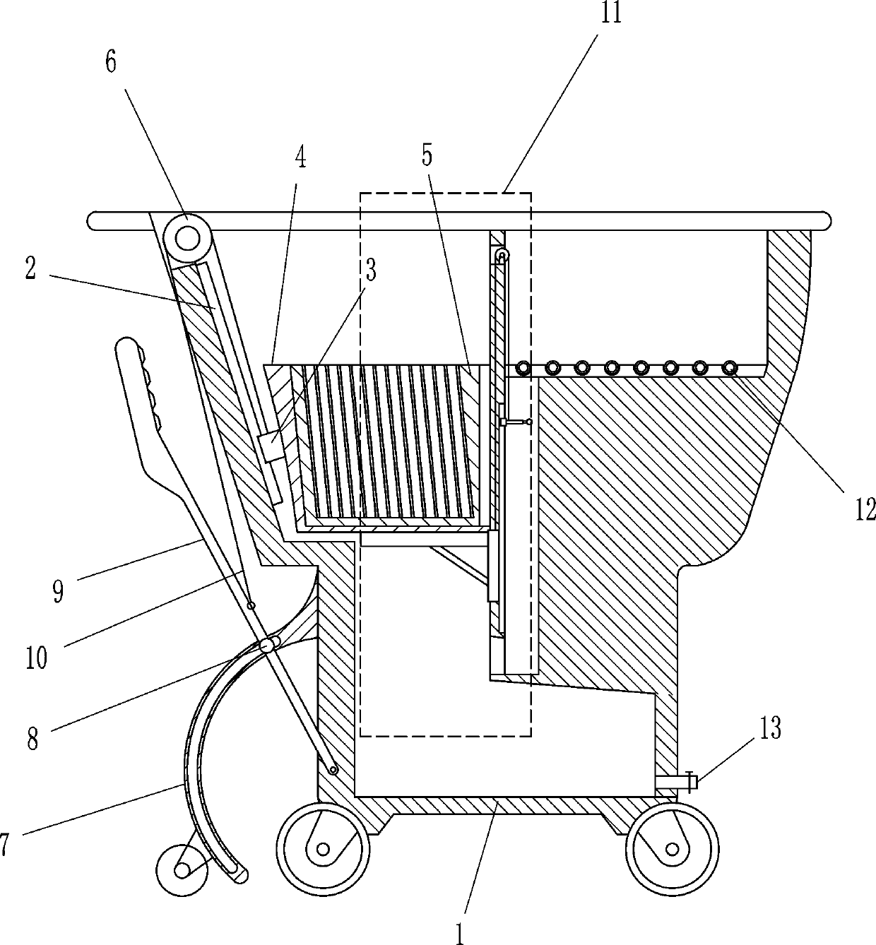
[0019] see figure 1 , figure 2 , image 3 and Figure 4 , a ceramic tile soaking device for construction, including a soaking box 1, a first slide rail 2, a first slide block 3, a placement box 4, a spacer box 5, a directional wheel 6, an arc-shaped slide rail 7, a slide shaft 8, and a pedal 9. The first pull rope 10, the guide device 11, the rolling wheel 12 and the water outlet pipe 13, the upper part of the inner wall of the soaking tank 1 is connected with the first slide rail 2 by means of bolt connection, and the first slide rail 2 is slidably provided with a first Slider 3, the first slider 3 is provided with a placement box 4, the placement box 4 is placed with a spacer box 5, the top of the soaking box 1 is provided with a directional wheel 6, and the left side wall of the soaking box 1 is symmetrically provided with curved slide rails. 7. Sliding shaft 8 is installed on the arc-shaped slide rail 7, pedal 9 is installed on the left side wall of soaking tank 1, and...

Embodiment 2

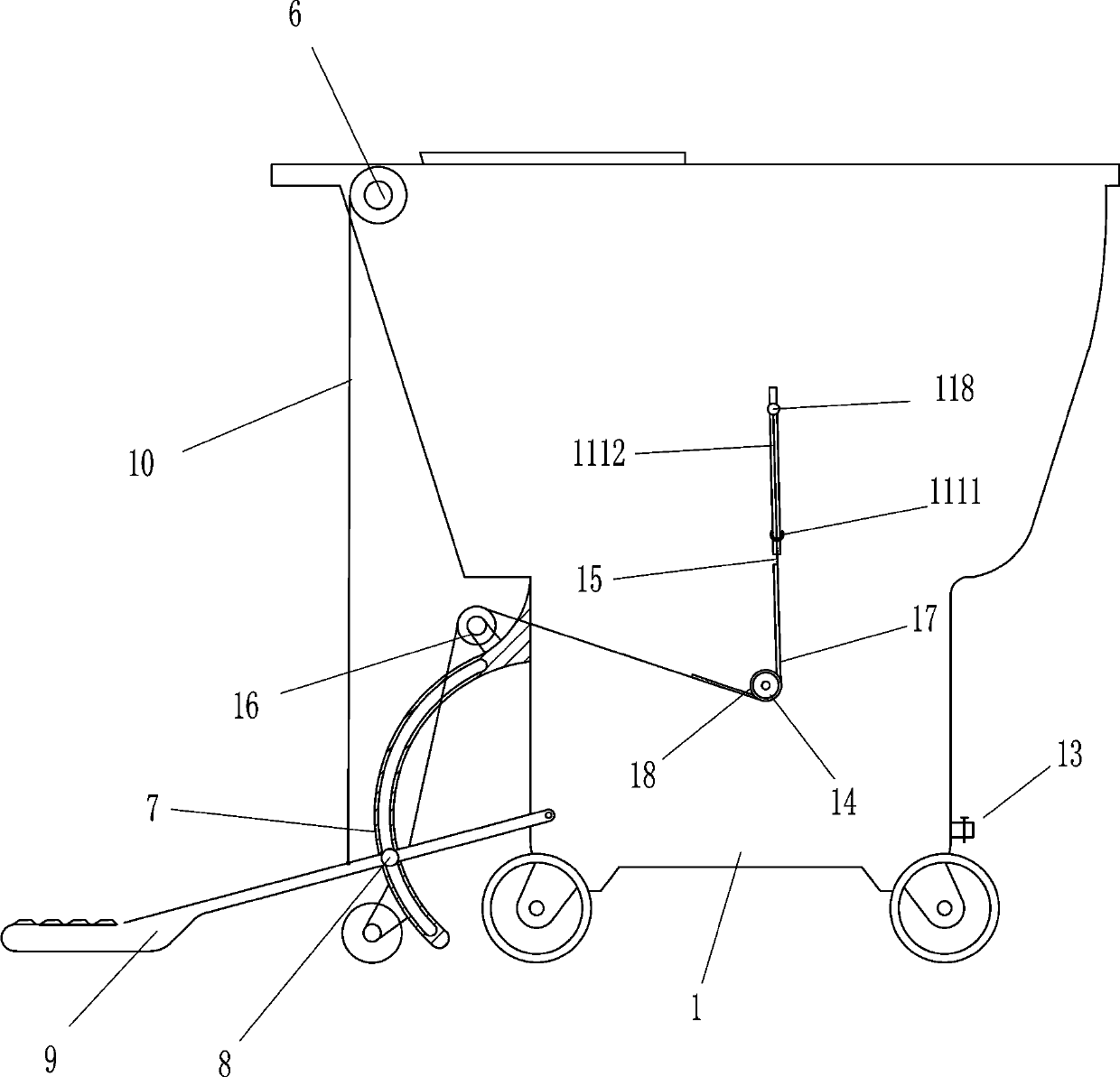
[0023] see figure 1 , figure 2 , image 3 and Figure 4 , on the basis of Embodiment 1, it also includes a first guide wheel 14, a rubber belt 15 and a second guide wheel 16, and the front and rear walls of the soaking tank 1 of the slot 1112 are provided with a first guide wheel through a connecting shaft rotation. Wheel 14, on the two curved slide rails 7, the second guide wheel 16 is connected by bolt connection, the sliding shaft 118 is provided with a rubber belt 15, and the rubber belt 15 walks around the first guide wheel on the same vertical surface 14 and the second guide wheel 16 are connected with pedal 9.

[0024] The working process of the present invention: when stepping on the pedal 9, the rubber belt 15 can drive the sliding shaft 118 to move downwards, and then drive the sliding plate 114 to move upwards, realizing linkage and convenient use.

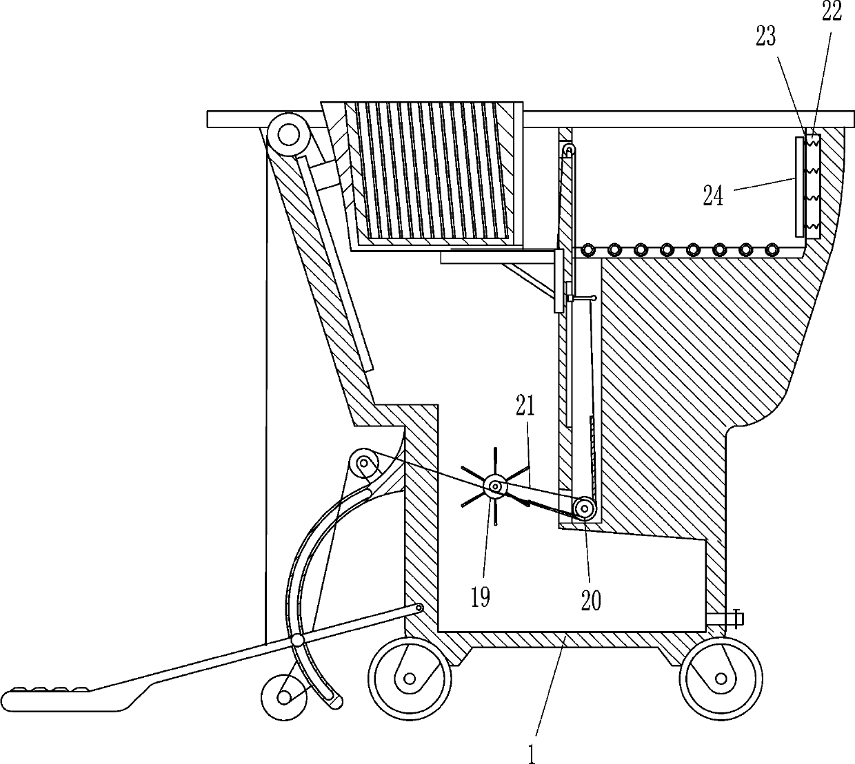
[0025]Also comprise tooth bar 17, ring gear 18, water wheel 19, pulley 20 and flat belt 21, on the rubber belt 1...


PUM


Abstract

The invention belongs to the technical field of building construction, and particularly relates to a soaking device for ceramic tiles for buildings. According to the technical problem, the ceramic tile soaking device for the buildings which is uniform in soaking, convenient to use and capable of conveniently assisting the paving of the wall surface is provided. The soaking device for ceramic tilesfor buildings comprises a soaking box, a first sliding rail, a first sliding block, a placing box, an interval box and the like; the upper part of the inner wall of the soaking box is provided with the first sliding rail, the first sliding block is slidably arranged on the first sliding rail, and the placing box is arranged on the first sliding block, and the interval box is placed on the placingbox. According to the ceramic tile soaking device, the effects that the soaking is uniform, the use is convenient, and assistance to the paving of the wall surface is facilitate are reached; when theceramic tile soaking device need to be used, the interval box filled with non-soaked ceramic tiles is put into the placing box, a pedal is loosened, the interval box and the placing box slide downwards under the action of gravity, and at the moment, water is injected into the interval box to soak the ceramic tiles.

Description

technical field [0001] The invention belongs to the technical field of building construction, and in particular relates to a ceramic tile soaking device for building. Background technique [0002] Ceramic tiles, also known as tiles, are a kind of acid and alkali resistant porcelain or stone formed by refractory metal oxides and semi-metal oxides through the process of grinding, mixing, pressing, glazing and sintering. Or decorative materials, called ceramic tiles. Its raw materials are mostly mixed with clay, quartz sand, etc. The history of tiles should be traced back to BC, when the Egyptians began to use tiles to decorate various types of houses. Clay bricks were dried in the sun or baked and then painted with a blue glaze extracted from copper. Tiles were also found in Mesopotamia BC. The tiles were decorated in blue and white stripes, and later came in a wider variety of styles and colors. China is the center of ceramic art, and as early as the Shang and Yin Dynastie...

Claims


Application Information

Patent Timeline
IPC IPC(8): E04F21/00
CPCE04F21/00
Inventor 吴昌泉
Owner 吴昌泉
Why Eureka
Try Eureka