Excavator load holding valve

A technology for load holding valves and excavators, which is applied to earth movers/shovels, mechanical equipment, servo motor components, etc., which can solve problems such as frequent action manipulation, increased equipment complexity, and increased equipment costs, and achieve improved use Life and service performance, guaranteed service life and service performance, and the effect of reducing wear and impact collision damage

Active Publication Date: 2021-04-06
LINYI JINLI HYDRAULIC TECH
View PDF10 Cites 0 Cited by
  • Summary
  • Abstract
  • Description
  • Claims
  • Application Information

AI Technical Summary

Problems solved by technology

However, the load holding valves disclosed in the above two patents have the following technical problems: 1. They are all plate valve structures, so they need to be fixedly installed on the bracket with screws during actual use, and then pass through the pipeline and oil cylinder and multiple valves. 2. When controlling the lifting and lowering of the oil cylinder, the load holding valves disclosed in the above two patents are both It is realized by controlling the repeated opening and closing actions of a spool, and the frequent operation of construction machinery will increase the opening and closing times of the corresponding spool, thereby aggravating the wear of the spool, resulting in poor sealing and leakage , which ultimately leads to shortened service life of the entire valve; 3. When the oil cylinder is in a long-term static state and the pressure in the oil cylinder rises due to the rise in oil temperature, the load holding valves disclosed in the above two patents cannot realize the increase in oil pressure. High limiting effect, at this time, in order to prevent the oil cylinder seal ring and pipeline from being damaged due to the continuous increase of oil pressure, it is usually necessary to configure a separate safety valve, which not only increases the complexity of the equipment, but also increases the cost of the equipment

Method used


Image

  • Excavator load holding valve
  • Excavator load holding valve
  • Excavator load holding valve

Examples


Embodiment Construction

[0030] The present invention will be further described in detail below in conjunction with the accompanying drawings and embodiments.

[0031] Such as Figure 1-6 Shown is a preferred embodiment of the present invention.

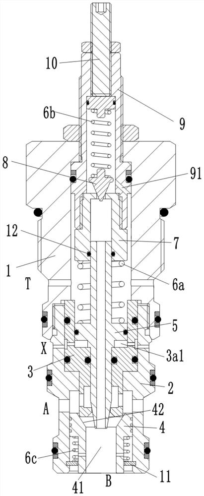
[0032] An excavator load holding valve comprising

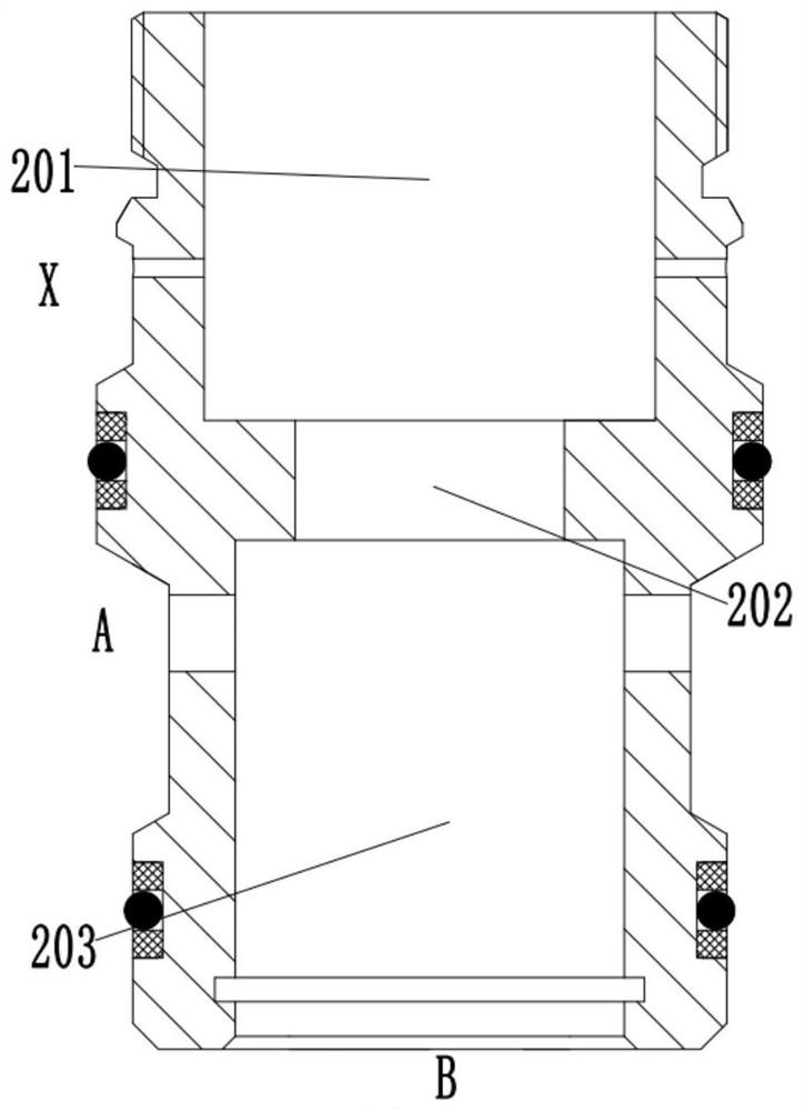
[0033] The valve sleeve 2 is provided with a valve sleeve through hole extending axially through the valve sleeve 2, and the valve sleeve through hole includes a first valve sleeve through hole section 201, a second valve sleeve through hole section 202 and a second valve sleeve through hole section from top to bottom. Three valve sleeve through-hole sections 203, the side wall of the valve sleeve 2 is provided with a control oil port X communicating with the first valve sleeve through-hole section 201 and a first oil port communicating with the third valve sleeve through-hole section 203 A, the lower opening of the through hole section 203 of the third valve sleeve constitutes the second oil port B.

[...


PUM


Abstract

The invention relates to an excavator load holding valve, which comprises a valve sleeve, which is provided with a first oil port and a second oil port; a screw sleeve, which is threadedly connected to the upper end of the valve sleeve; and a valve seat, which is fixedly connected in the valve sleeve; The one-way valve core is slidingly arranged in the valve sleeve, and has an inner tapered surface to form a line seal with the lower end surface of the valve seat; the adjustment sleeve is threaded on the screw sleeve; the overflow valve seat is fixedly connected to the lower end of the adjustment sleeve; the control The spool, slides in the valve seat; the control spring; the relief valve assembly. The excavator load holding valve of the present invention has the advantages of simple structure, compact volume, convenient integration, long service life and safety overflow function.

Description

technical field [0001] The invention belongs to the technical field of excavators, in particular to an excavator load holding valve. Background technique [0002] The load holding system is an essential hydraulic system in the hydraulic system of the excavator. It is used to ensure that the excavator can maintain a certain action for a long time, such as the maintenance of the stick and the boom in the excavator. It can ensure that the excavator can complete some basic functions. lifting operations. The load holding valve is the most critical part of the load holding system, and its quality directly affects the quality of the excavator's hoisting operation, and even threatens the personal safety of the staff. Therefore, the quality of the load holding valve will directly affect the performance of the load holding system. However, the load holding valve we use currently has a certain internal leakage and the internal leakage is relatively large. This large amount of intern...

Claims


Application Information

Patent Timeline
Patent Type & Authority Patents(China)
IPC IPC(8): F15B13/01F15B13/02E02F9/22
CPCE02F9/2267F15B13/01F15B13/024F15B13/027F15B2013/004
Inventor 武芳
Owner LINYI JINLI HYDRAULIC TECH
Why Eureka
Try Eureka