Constant temperature water mixing valve

A thermostatic mixing valve and valve body technology, applied in valve details, multi-port valves, valve devices, etc., can solve the problems of difficult adjustment, high motor power, complex structure, etc., to achieve fast response, small driving force, Accurate temperature adjustment

Inactive Publication Date: 2020-02-04
重庆康乃宝科技有限公司
View PDF0 Cites 0 Cited by
  • Summary
  • Abstract
  • Description
  • Claims
  • Application Information

AI Technical Summary

Problems solved by technology

[0002] At present, most of the mixing valves on the market are manual mixing valves. There are such problems in manual mixing valves. One is that it is not easy to adjust accurately. There are also special mixing valves, many of which are mechanical. The structure of the mechanical thermostatic mixing valve body is usually very complicated. If there are too many impurities in the water, it will become insensitive after a long time, or it cannot be used at all. Electric daily I didn’t find it in my life. Through patent inquiry, I found that there is an electric mixing valve, which drives the gear through a stepping motor, and the gear drives the valve body of an ordinary mixing valve. What’s wrong with this mixing valve? The volume comparison It is large and the structure is relatively complicated. If it is used in household appliances, the cost is high and it takes up a lot of space. If it is not directly driven by gears, due to the relatively large driving force, the required motor power will be relatively large, which will lead to high cost and large volume. Usually we turn the water mixing valve by hand, in fact, it is turned by the handle on the water mixing valve. The handle is actually a lever. It is impossible to use the handle directly with the motor drive, so the force required for the motor drive is large, and According to the structural characteristics of ordinary water mixing valves, if the pressure is higher, the driving force will be greater, so this electric muddy water valve is not advisable

Method used


Image

  • Constant temperature water mixing valve
  • Constant temperature water mixing valve
  • Constant temperature water mixing valve

Examples


Embodiment Construction

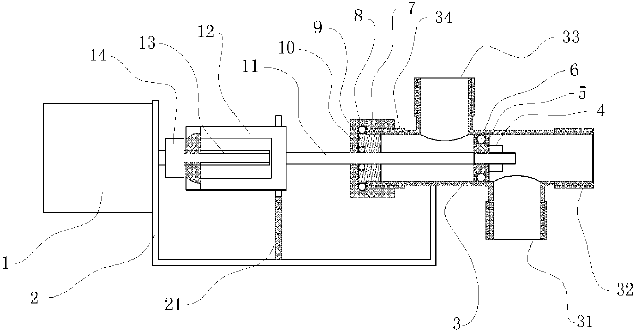
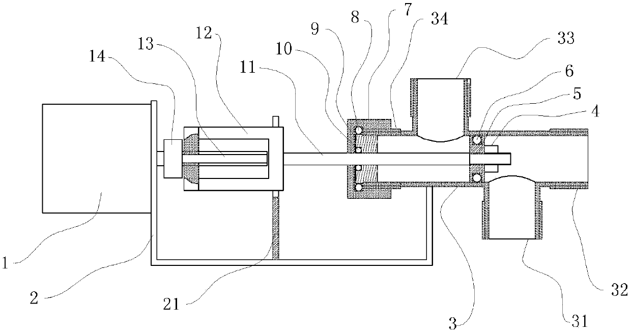
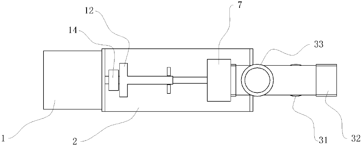
[0013] refer to figure 1 , a thermostatic water mixing valve of the present invention includes a stepper motor 1, a bracket 2, and a valve body 3, the valve body 3 is provided with four threaded ports, the port 32 is a hot water pipe port, and the port 33 is a cold water pipe port , the interface 31 is the water outlet of the mixing valve, the inside of the valve body 3 is a cylindrical surface, the valve core 5 is fixed on the valve stem 11, and the components composed of the valve core 5 and the valve stem 11 form a sliding fit with the inner surface of the valve body 3 , The spool 5 is also provided with an annular groove, the sealing ring 6 is stuck in the annular groove, the right side of the spool 5 is provided with a locking nut 4, and the locking nut locks the spool 5 by the screw thread at the right end of the valve stem.

[0014] The valve body 3 is fixed on the bracket 2, the interface 34 on the valve body 3 is provided with a sealing nut 7, the valve stem 11 passes...


PUM


Abstract

The invention discloses a constant temperature water mixing valve which includes a stepping motor 1, a bracket 2, a valve body 3, a valve element 5 and a screw rod and nut driving mechanism, wherein four close nipples are arranged on the valve body 3; an interface 32 is a hot water pipe interface; an interface 33 is a cold water pipe interface; an interface 31 is a water outlet of the water mixingvalve; an interface 34 is a valve element driving port; a sealing nut is arranged on the interface 34; the stepping motor is connected with a screw rod through a coupling; the screw rod is used for driving a nut so as to drive a valve rod and the valve element to move; during use, a temperature sensing probe is arranged at a water outlet pipe, and a controller controls the valve element to move according to the temperature of water flowing out so as to adjust the temperature of mixed water to be equal to the setting temperature. The water mixing valve is simple in structure, reliable to use,low in driving force, small in occupation space, low in cost, accurate in temperature adjustment, and quick in response, is an ideal constant temperature water mixing valve, and can be widely appliedto domestic appliances.

Description

technical field [0001] The invention relates to a water mixing valve, in particular to a constant temperature water mixing valve. Background technique [0002] At present, most of the mixing valves on the market are manual mixing valves. There are such problems in manual mixing valves. One is that it is not easy to adjust accurately. There are also special mixing valves, many of which are mechanical. The structure of the mechanical thermostatic mixing valve body is usually very complicated. If there are too many impurities in the water, it will become insensitive after a long time, or it cannot be used at all. Electric daily I didn’t find it in my life. Through patent inquiry, I found that there is an electric mixing valve, which drives the gear through a stepping motor, and the gear drives the valve body of an ordinary mixing valve. What’s wrong with this mixing valve? The volume comparison It is large and the structure is relatively complicated. If it is used in household...

Claims


Application Information

Patent Timeline
Patent Type & Authority Applications(China)
IPC IPC(8): F16K11/065F16K31/04F16K31/44
CPCF16K11/0655F16K31/04F16K31/44
Inventor 赵怀方
Owner 重庆康乃宝科技有限公司
Why Eureka
Try Eureka