A Short Delay Trigger Ignition Circuit
A technology of ignition circuit and delay circuit, applied in blasting and other directions, can solve the problems of complex principle, high power performance requirements, inability to reliably start stability and other problems, and achieve the effect of low load capacity requirements, good stability, and stable low temperature operation.
- Summary
- Abstract
- Description
- Claims
- Application Information
AI Technical Summary
Problems solved by technology
Method used
Image
Examples
Embodiment Construction
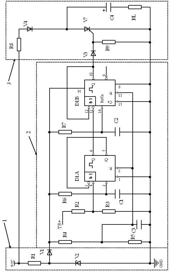
[0024] as Figure 1 As shown, the present invention short delay trigger ignition circuit comprises a power supply buck circuit 1, a delay circuit 2 and a firing circuit 3. VCC stands for power supply, which can range from 10V to 32V or even wider. GND represents the power supply reference ground. TR+ indicates the input of the trigger signal, the input trigger signal is a voltage pulse, and the rising edge is valid. RL indicates an electric fire product to be ignited or detonated.
[0025] The power buck circuit 1 consists of resistor R1, diode V1, and regulated diode V2. One end of resistor R1 is connected to the power supply VCC, the other end is connected to the positive electrode of diode V1 and the negative pole of the voltage diode V2, and the positive pole of the voltage diode V2 is connected to the supply reference GND. The negative electrode of diode V1 is the output of the power supply buck circuit 1 and the power supply terminal of the delay circuit 2.
[0026] This cir...
PUM
 Abstract
Description
Claims
Application Information
 - R&D
- Intellectual Property
- Life Sciences
- Materials
- Tech Scout
- Unparalleled Data Quality
- Higher Quality Content
- 60% Fewer Hallucinations
Browse by: Latest US Patents, China's latest patents, Technical Efficacy Thesaurus, Application Domain, Technology Topic, Popular Technical Reports.
© 2025 PatSnap. All rights reserved.Legal|Privacy policy|Modern Slavery Act Transparency Statement|Sitemap|About US| Contact US: help@patsnap.com


