
Short delay trigger ignition circuit

A technology of ignition circuit and delay circuit, applied in blasting and other directions, can solve the problems of complex principle, high power performance requirements, inability to reliably start stability and other problems, and achieve the effect of low load capacity requirements, good stability, and stable low temperature operation.

Active Publication Date: 2020-02-04
SUZHOU R&D CENT OF NO 214 RES INST OF CHINA NORTH IND GRP
View PDF8 Cites 0 Cited by
  • Summary
  • Abstract
  • Description
  • Claims
  • Application Information

AI Technical Summary

Problems solved by technology

[0003] The current delay trigger ignition circuit mostly adopts the method of oscillation counting or MCU software to realize the delay, which may not start reliably or have poor stability at low temperature, the principle is complicated, the performance requirements of the power supply are high, and it is difficult to carry out miniaturization and secondary integration. And other issues

Method used


Image

  • Short delay trigger ignition circuit
  • Short delay trigger ignition circuit

Examples


Embodiment Construction

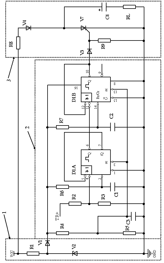
[0024] Such as figure 1 As shown, the short-delay trigger ignition circuit of the present invention includes a power step-down circuit 1 , a delay circuit 2 and an ignition circuit 3 . VCC represents the power supply, and its voltage range can be from 10V to 32V or even wider. GND means power reference ground. TR+ indicates the trigger signal input terminal, the input trigger signal is a voltage pulse, and the rising edge is valid. RL means the electro-explosive device to be ignited or detonated.

[0025] The power step-down circuit 1 is composed of a resistor R1, a diode V1 and a Zener diode V2. One end of the resistor R1 is connected to the power supply VCC, the other end is connected to the anode of the diode V1 and the cathode of the voltage diode V2, and the anode of the voltage diode V2 is connected to the power reference ground GND. The cathode of the diode V1 is the output of the power step-down circuit 1 and also the power supply terminal of the delay circuit 2 . ...


PUM


Abstract

The invention discloses a short delay trigger ignition circuit. The short delay trigger ignition circuit comprises a power supply voltage reduction circuit, a delay circuit and an ignition circuit; the power supply voltage reduction circuit reduces the supply voltage of a power supply to the operating voltage of the delay circuit; the delay circuit adopts two-stage monostable triggers, the primarymonostable trigger performs delaying according to a pulse signal loaded by a trigger signal input end, and the secondary monostable trigger outputs a trigger signal to trigger the ignition circuit after delaying is performed for a set time; the ignition circuit comprises a charging current limiting resistor, an energy storage capacitor and an electric explosive device connected in series betweenthe power supply and ground; the two ends of the energy storage capacitor and the electric explosive device are connected with a thyristor in parallel; and when the trigger signal input end loads thepulse signal to enable the delay circuit to output the trigger signal to trigger the thyristor to be turned on, the energy storage capacitor performs discharging on the electric explosive device through the thyristor, and the electric explosive device is detonated and ignited. The short delay trigger ignition circuit can be reliably started and stably operated in a wide temperature range, especially at low temperature, and can be operated in a wide power supply range.

Description

technical field [0001] The invention relates to a delay trigger ignition circuit, in particular to a short delay trigger which can work stably in a wide temperature range, especially at low temperature, has a relatively simple principle, can work in a wide power supply voltage range, and can output a large current ignition circuit. Background technique [0002] In the fuze electronic system, it needs to be able to start reliably and work stably in a wide temperature range, especially at low temperature (such as -55°C), and work in a wide power supply voltage range from several volts to tens of volts. A so-called short-delay trigger ignition circuit that is simple and suitable for miniaturized secondary integration with a delay of several milliseconds. [0003] The current delay trigger ignition circuit mostly adopts the method of oscillation counting or MCU software to realize the delay, which may not start reliably or have poor stability at low temperature, the principle i...

Claims


Application Information

Patent Timeline
Patent Type & Authority Applications(China)
IPC IPC(8): F42D1/055
CPCF42D1/055
Inventor 冯业胜
Owner SUZHOU R&D CENT OF NO 214 RES INST OF CHINA NORTH IND GRP
Learn More