Industrial flow instrument for industrial production, and use method thereof

A flowmeter and industrial technology, applied in the field of industrial flow equipment, can solve the problems of damage to the flowmeter, reduce the service life of the flowmeter, and the flowmeter is easily disturbed by magnetic fields, and achieve the effect of easy installation, prolonging the service life and measuring accuracy.

Active Publication Date: 2020-02-04
JIANGSU MICRO WAVE ELECTRONICS TECH
View PDF9 Cites 3 Cited by
  • Summary
  • Abstract
  • Description
  • Claims
  • Application Information

AI Technical Summary

Problems solved by technology

[0004] The purpose of the present invention is to provide an industrial flow meter for industrial production and its use method. In order to overcome the above-mentioned installation position of the existing industrial flow meter for industrial production, attention should be paid when the flow meter is installed on motors, transformers, etc. that are likely to cause electromagnetic interference. When the flowmeter is near the transmitter or other power sources, the flowmeter is easily disturbed by the magnetic field; if the flowmeter is directly installed on a freely vibrating pipeline, the vibration of the pipeline itself will be transmitted to the flowmeter to cause the vibration of the flowmeter, which will easily cause damage to the flowmeter and reduce the The service life of the flow meter also results in inaccurate measured data; at the same time, the flow meter needs to consume power during use. When the flow meter is in use, it is necessary to pay attention to the remaining power of the built-in battery of the flow meter to avoid the technology that the flow meter automatically stops working when the power is exhausted. question

Method used


Image

  • Industrial flow instrument for industrial production, and use method thereof
  • Industrial flow instrument for industrial production, and use method thereof
  • Industrial flow instrument for industrial production, and use method thereof

Examples


Embodiment Construction

[0035] The technical solutions of the present invention will be clearly and completely described below in conjunction with the embodiments. Apparently, the described embodiments are only some of the embodiments of the present invention, not all of them. Based on the embodiments of the present invention, all other embodiments obtained by persons of ordinary skill in the art without creative efforts fall within the protection scope of the present invention.

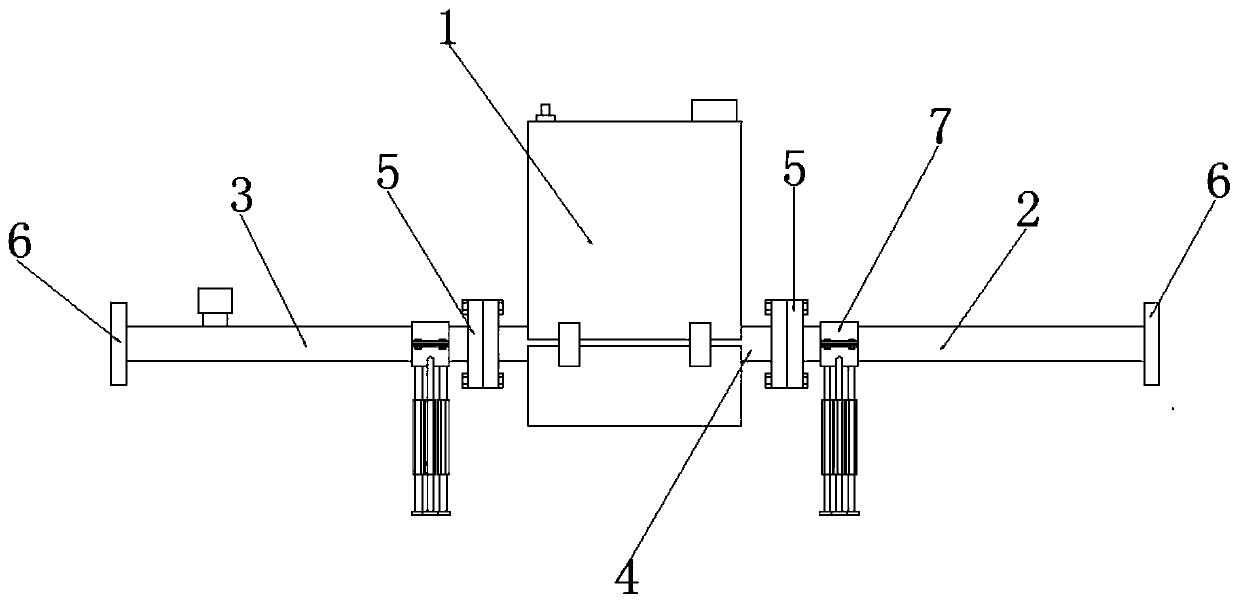
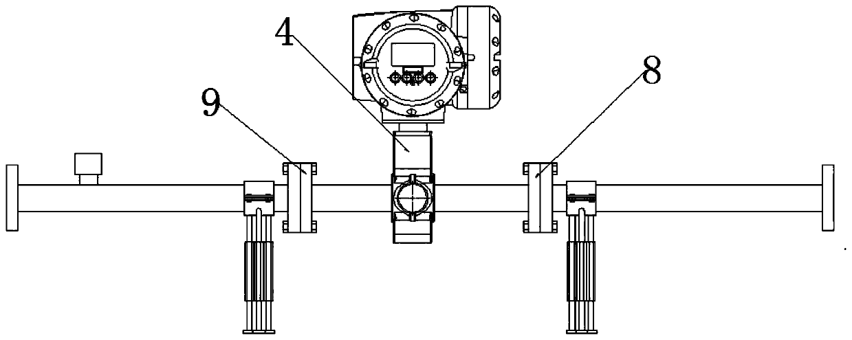
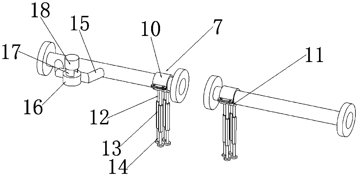
[0036] see Figure 1-7 As shown, an industrial flow meter for industrial production includes a shielding box 1, a first buffer pipe 2, a second buffer pipe 3, a flow meter 4 and a fixing mechanism 7, and the first buffer pipe 2 is installed at one end of the flow meter 4, A second buffer pipe 3 is installed at the other end of the flowmeter 4, and a shielding box 1 is installed outside the flowmeter 4;

[0037] The first buffer pipe 2 and the second buffer pipe 3 are equipped with a fixing mechanism 7 near the end of the f...


PUM


Abstract

The invention discloses an industrial flow instrument for industrial production. The industrial flow instrument comprises a shielding box, a first buffer tube, a second buffer tube, a flowmeter and afixing mechanism, wherein the first buffer tube is installed at one end of the flowmeter, the second buffer tube is installed at the other end of the flowmeter, and the shielding box is installed outside the flowmeter. The normal use of the flowmeter near a motor, a transmitter or other power supplies capable of easily causing electromagnetic interference can be guaranteed through the shielding box; a cooling mechanism can maintain the normal temperature in the shielding box; the first buffer tube and the second buffer tube cannot drive the flowmeter to produce vibration in the normal work theservice life of the flowmeter is prolonged, the measurement precision is improved; a generator is operated to generate electricity, the generated electricity is transmitted to an electric connector through a lead, and is supplied to an instrument for use after the voltage is regulated by the voltage regulator, the condition of electricity exhaustion during operation is avoided, and the industrialflowmeter can continuously operate.

Description

technical field [0001] The invention relates to the field of industrial flow devices, in particular to an industrial flow meter for industrial production and a method for using the same. Background technique [0002] Measurement is the eye of industrial production. Flow measurement is one of the components of measurement science and technology. It is closely related to national economy, national defense construction, and scientific research. Doing this work well will ensure product quality, improve production efficiency, and promote The development of science and technology plays an important role, especially in the current era of energy crisis and industrial production automation, the status and role of flowmeters in the national economy are more obvious. [0003] Attention should be paid to the installation position of the industrial flowmeter used in the existing industrial production. When the flowmeter is installed near the motor, transmitter or other power sources that...

Claims


Application Information

Patent Timeline
Patent Type & Authority Applications(China)
IPC IPC(8): G01F15/14G01F15/00F03B13/00
CPCF03B13/00G01F15/00G01F15/14
Inventor 刘建兵徐峰
Owner JIANGSU MICRO WAVE ELECTRONICS TECH
Why Eureka
Try Eureka