Middle seal punching die structure

A technology for punching dies and switching parts, applied in the field of punching dies, which can solve problems such as low work efficiency, aging and deformation of punching machines and lower modules, and potential safety hazards, so as to improve use efficiency, increase safety, and improve use efficiency Effect

Pending Publication Date: 2021-06-11
上海探见智能家居有限公司
View PDF0 Cites 2 Cited by
  • Summary
  • Abstract
  • Description
  • Claims
  • Application Information

AI Technical Summary

Problems solved by technology

[0003] In the processing of existing door and window center seals, if the processing method of sawing first and then sawing and milling is adopted, there are problems such as long processing time and low work efficiency
[0004] If the processing method of continuous punching is adopted, it is necessary to complete a single punching of the workpiece in the first concave film first, and then take it out after punching and put it into the second concave film for secondary punching. Although this method is relatively The processing method of sawing first and then sawing and milling is efficient, but during the processing, the punching machine needs to be switched on and off repeatedly, and the operator needs to be facing the die directly below the punching machine to replace the workpiece, which has certain potential safety hazards
[0005] In addition, when the existing punching machine is in operation, a large amount of heat is generated due to repeated friction between the punching machine and the concave film, and the heat cannot be dissipated in time after long-term use, which may easily cause the punching machine and the lower module to be damaged. Aging deformation occurs at high temperature, affecting product quality

Method used


Image

  • Middle seal punching die structure
  • Middle seal punching die structure
  • Middle seal punching die structure

Examples


Embodiment Construction

[0034] The following will clearly and completely describe the technical solutions in the embodiments of the present invention with reference to the accompanying drawings in the embodiments of the present invention. Obviously, the described embodiments are only some, not all, embodiments of the present invention. Based on the embodiments of the present invention, all other embodiments obtained by persons of ordinary skill in the art without making creative efforts belong to the protection scope of the present invention.

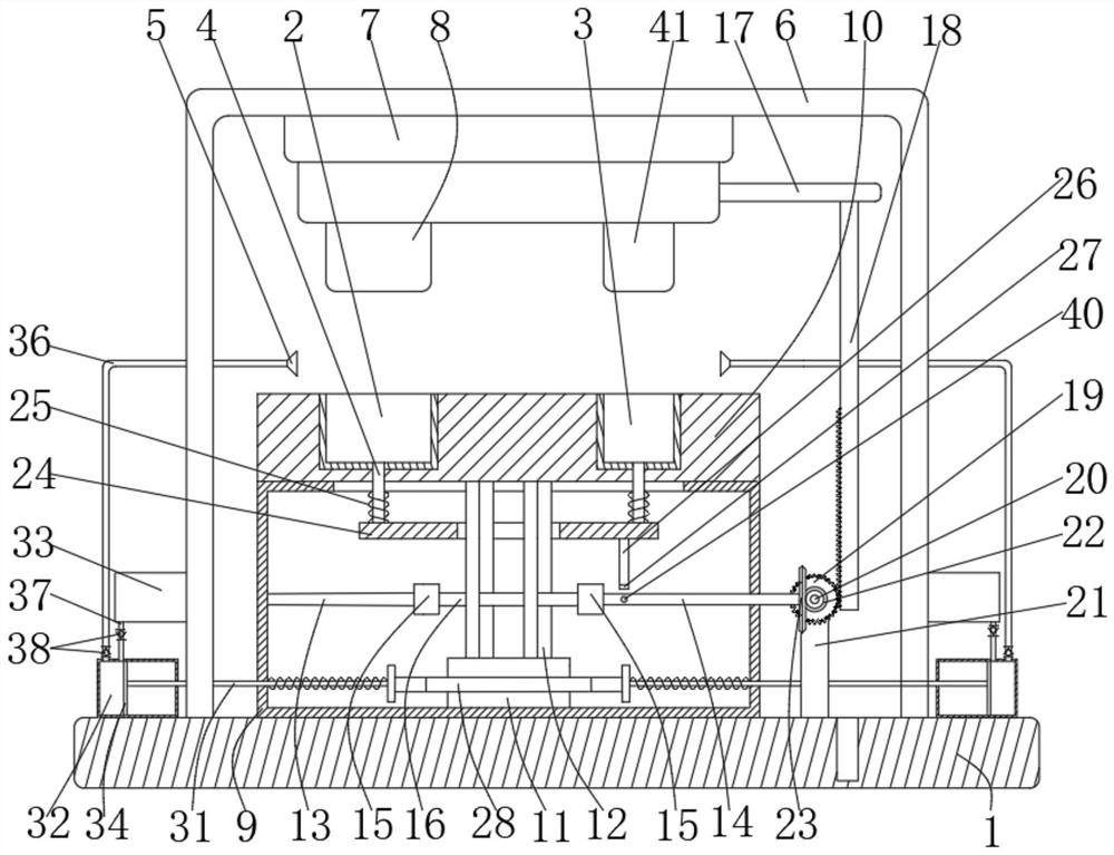
[0035] Such as Figure 1 to Figure 8 As shown, the present invention provides a middle seal die-cutting die structure, such as figure 1 As shown, it includes the bottom plate 1 and the die-cutting parts, and also includes two concave films 1 2 and two concave films 2 3, and drives the two concave films 1 2 and two concave films 2 3 to face the punching in turn. Cut the toggle widget directly below the widget.

[0036] The switching part is linked with the up...


PUM


Abstract

The invention discloses a middle seal punching die structure. The middle seal punching die structure comprises a bottom plate and a punching part, and a switching part is linked with the upward moving process of the punching part through a linkage part I. The middle seal punching die structure further comprises four ejector rods used for ejecting workpieces in two lower concave dies I and two lower concave dies II, and the four ejector rods are in transmission connection with the switching part through a linkage part II. The middle seal punching die structure further comprises a spraying mechanism capable of spraying towards the direction of the workpieces through a spray head when the switching part is switched. According to the middle seal punching die structure, through vertical movement of a punching machine, the two groups of concave dies I and lower concave dies II can be switched back and forth, the concave dies can be staggered from the position under the punching machine after being deflected every time the workpieces are taken out, so that the safety of a user is guaranteed when the workpieces are replaced, and the situation that the working efficiency is reduced due to repeated shutdown is avoided.

Description

technical field [0001] The invention relates to the technical field of punching dies, in particular to a middle-seal punching die structure. Background technique [0002] With China's rapid development in recent years, people's demand for doors and windows is increasing. In the traditional manufacturing of aluminum alloy doors and windows, the implementation of automation and mechanization is still insufficient. [0003] When processing the center seal of existing doors and windows, if the processing method of sawing first and then sawing and milling is adopted, there are problems of long processing time and low work efficiency. [0004] If the processing method of continuous punching is adopted, it is necessary to complete a single punching of the workpiece in the first concave film first, and then take it out after punching and put it into the second concave film for secondary punching. Although this method is relatively The processing method of sawing first and then sawi...

Claims


Application Information

Patent Timeline
Patent Type & Authority Applications(China)
IPC IPC(8): B21D28/14B21D28/04B21D37/16B21D53/74
CPCB21D28/04B21D28/14B21D37/16B21D53/74
Inventor 欧阳雪崔阳季荣
Owner 上海探见智能家居有限公司
Why Eureka
Try Eureka