
Tire shaft dynamic balance detection and correction device

A correction device and tire technology, applied in the static/dynamic balance test, measuring device, machine/structural component test, etc., can solve the problems of shaft deformation and bending, unfavorable detection efficiency, cumbersome disassembly and installation process, etc., and achieve simplification The process of installation and disassembly, the effect of improving detection efficiency, labor-saving and convenient installation

Inactive Publication Date: 2020-02-04
刘咏
View PDF7 Cites 5 Cited by
  • Summary
  • Abstract
  • Description
  • Claims
  • Application Information

AI Technical Summary

Problems solved by technology

[0003] During the detection and calibration process of the tire balancer, due to the heavy weight of the tire, it needs to consume a lot of manpower to install it. At the same time, during the installation, the tire suddenly puts weight on the shaft, which is easy to cause the shaft to deform and bend. The installation accuracy of the tire and the rotating shaft is high. When the tire is adjusted on the rotating shaft due to its own weight, it is easy to cause friction on the outer wall of the rotating shaft, which in turn affects the detection accuracy of the balancing machine; and the installation inner diameter of different tires is different. At this time, it needs to be replaced. The traditional balancing machine needs to disassemble the shaft as a whole, which makes the process of disassembly and installation more cumbersome, which is not conducive to improving the detection efficiency
[0004] To this end, a tire shaft dynamic balance detection and correction device is provided to solve the problem of tire installation on the balance machine and the coordination problem with the shaft

Method used


Image

  • Tire shaft dynamic balance detection and correction device
  • Tire shaft dynamic balance detection and correction device
  • Tire shaft dynamic balance detection and correction device

Examples


Embodiment Construction

[0026] The following will clearly and completely describe the technical solutions in the embodiments of the present invention with reference to the accompanying drawings in the embodiments of the present invention. Obviously, the described embodiments are only some, not all, embodiments of the present invention. Based on the embodiments of the present invention, all other embodiments obtained by persons of ordinary skill in the art without making creative efforts belong to the protection scope of the present invention.

[0027] see Figure 1 to Figure 5 , the present invention provides a technical solution:

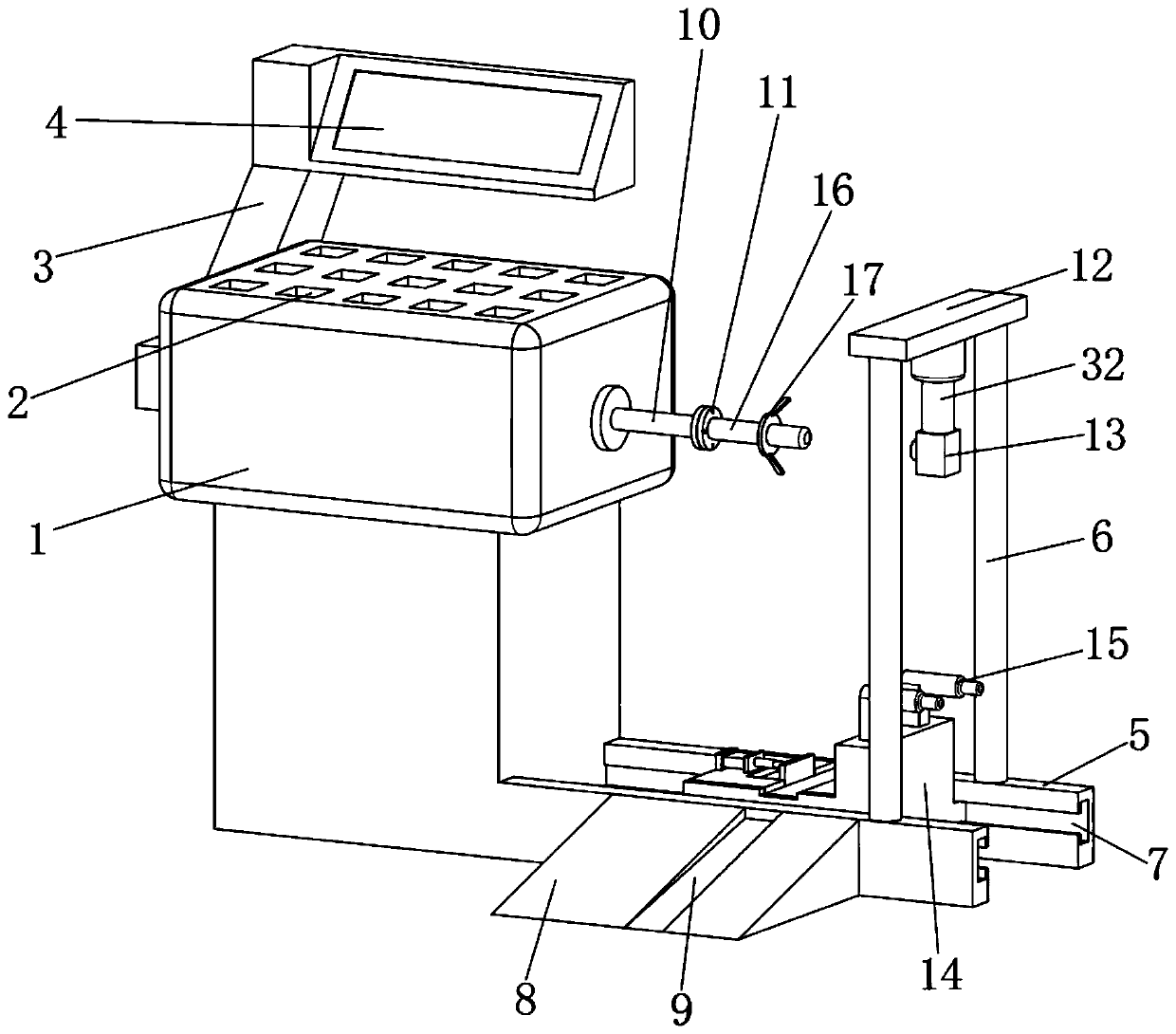
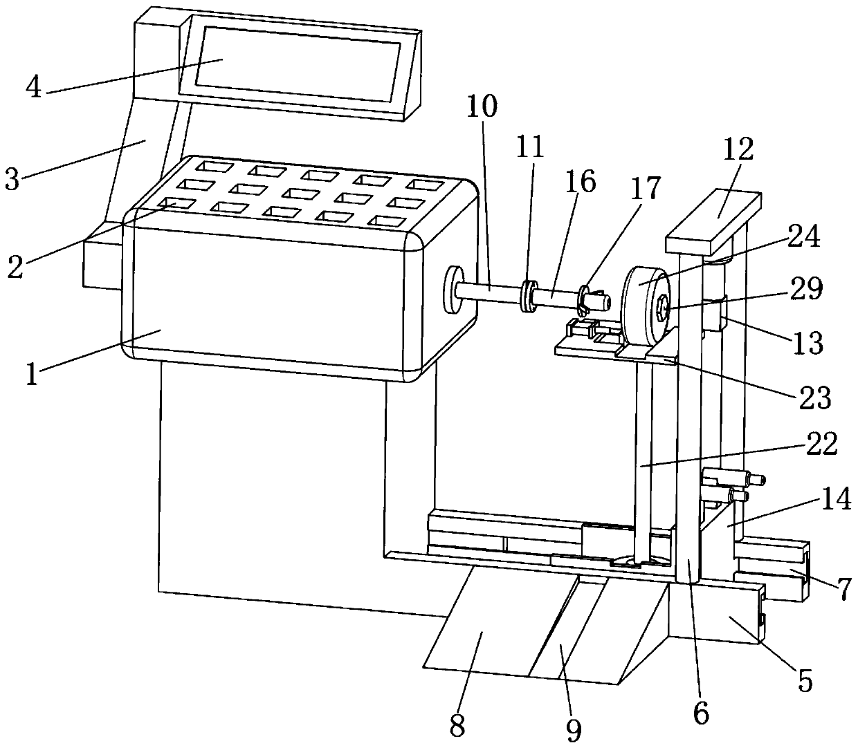
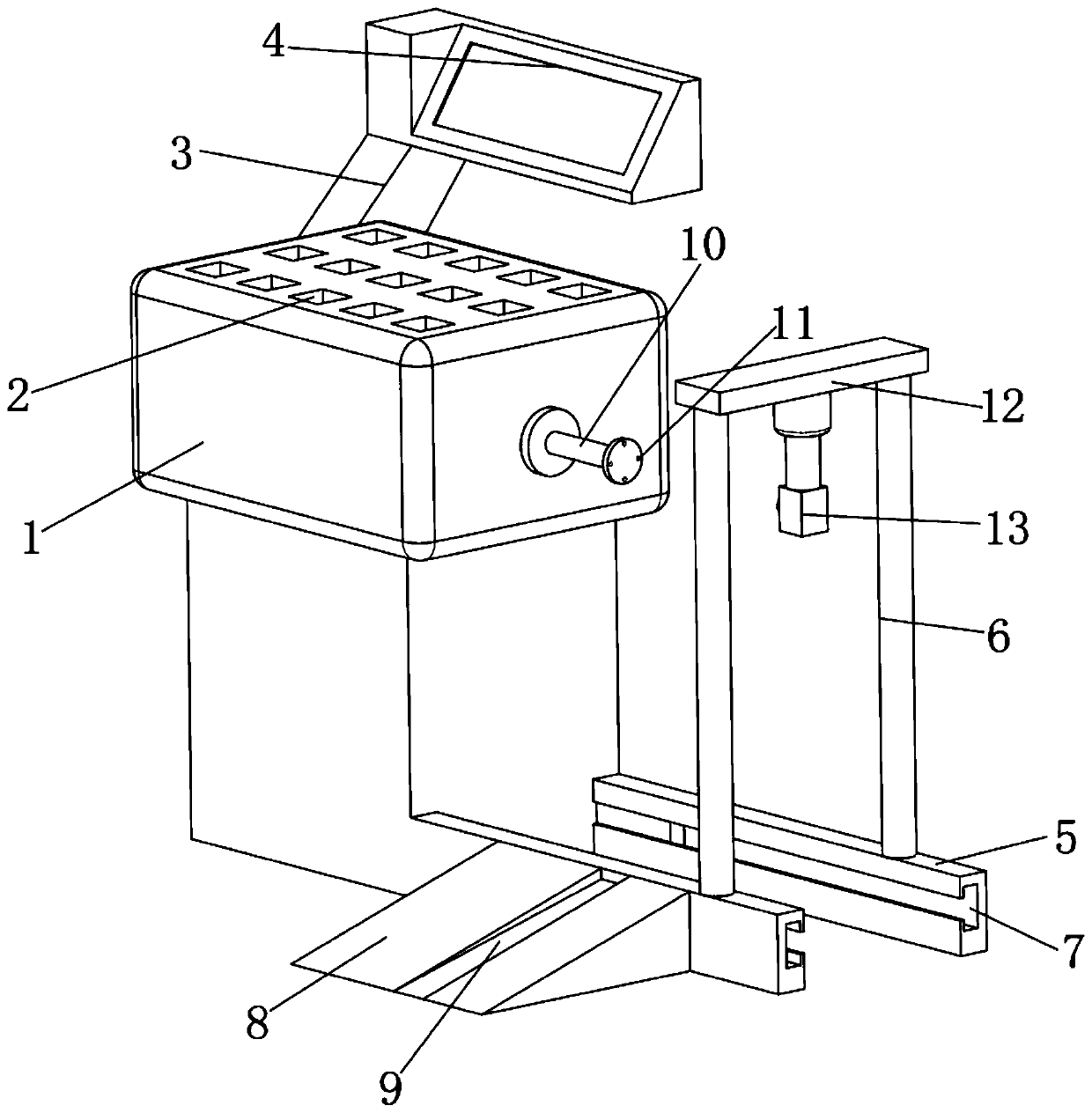
[0028] A tire shaft dynamic balance detection and correction device, including a balance host 1, a material frame 2 is arranged on the upper end surface of the balance host 1, a rocker arm 3 is installed on the left end surface of the balance host 1, and the lower end of the rocker arm 3 is electrically connected to the balance The host 1 and the rear end of the rocker a...


PUM


Abstract

The invention relates to the technical field of tire balancing machines, in particular to a tire shaft dynamic balance detection and correction device. The tire shaft dynamic balance detection and correction device comprises a balancing main machine, a material frame is arranged on the upper end face of the balancing main machine, a rocker arm is rotatably mounted on the left end face of the balancing main machine, a main rotating shaft is arranged on the upper side of the right end face of the balancing main machine, and a pair of guiding rails which are symmetrically in the front-rear direction and extend rightwards are vertically arranged at the lower end of the right side of the balancing main machine. The tire shaft dynamic balance detection and correction device has the beneficial effects that by arranging an auxiliary shaft adopting a connecting flange for connecting, quick mounting between the auxiliary shaft and the main rotating shaft is achieved, the detecting efficiency isfurther improved, and the mounting and demount processes are simplified; by arranging a sliding trolley with the lifting effect, meanwhile, a hydraulic cylinder is utilized to realize lifting of tires, and the purposes of labor saving and convenient and quick mounting are achieved; and by arranging cooperation of a module and a laser emitter, the tires, the auxiliary shaft and the laser source arelocated on the same axis, thus the tires are accurately mounted, the abrasion to the outer wall of the rotating shaft by the tires is avoided, and the detection precision is improved.

Description

technical field [0001] The invention relates to the technical field of tire balancing machines, in particular to a tire shaft dynamic balance detection and correction device. Background technique [0002] The balancing machine is an instrument used to measure the unbalance of the rotor. The balancing machine belongs to the hard-supported balancing machine. The vibration on the bearing is reduced to the allowable range to achieve the purpose of reducing vibration, improving performance and improving product quality. [0003] During the detection and calibration process of the tire balancer, due to the heavy weight of the tire, it needs to consume a lot of manpower to install it. At the same time, during the installation, the tire suddenly puts weight on the shaft, which is easy to cause the shaft to deform and bend. The installation accuracy of the tire and the rotating shaft is high. When the tire is adjusted on the rotating shaft due to its own weight, it is easy to cause ...

Claims


Application Information

Patent Timeline
Patent Type & Authority Applications(China)
IPC IPC(8): G01M1/02G01M1/16
CPCG01M1/02G01M1/16
Inventor 刘咏
Owner 刘咏
Learn More