Insulated brake pull-rod

A brake lever and insulating rope technology, applied in the field of electric machinery, can solve problems such as poor control ability and user slippage

Inactive Publication Date: 2020-02-04
湖南望轶工程设备租赁有限公司
View PDF3 Cites 0 Cited by
  • Summary
  • Abstract
  • Description
  • Claims
  • Application Information

AI Technical Summary

Problems solved by technology

The existing insulated brake lever has a simple design and cannot only clamp high-voltage isolating switches, dropped fuses, etc., causing users to often slip off when operating, and the control ability is poor

Method used


Image

  • Insulated brake pull-rod

Examples


Embodiment Construction

[0012] A preferred embodiment of an insulating switch rod of the present invention will be described in detail below with reference to the accompanying drawings.

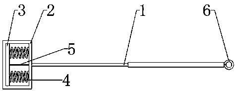
[0013] figure 1 Show the specific implementation of an insulating switch lever of the present invention: the insulating switch lever includes a freely expandable telescopic tube 1, one end of the telescopic tube 1 is provided with a rectangular frame-shaped switch frame 2, and the switch frame 2 passes through two The spring 4 is connected with the pressure plate 3, and the elongation force of the spring 4 forces the pressure plate 3 to be tightly attached to the inner wall of the shutter frame 2. The end of the pressure plate 3 close to the telescopic tube 1 is connected with an insulating rope 5, and the insulating rope 5 passes through the shutter frame. 2 and telescopic tube 1 are connected with pull ring 6.

[0014] Such as figure 1 As shown, the telescopic tube 1 is made of insulating material with good insu...


PUM


Abstract

The invention discloses an insulated brake pull-rod, and relates to the field of electrical machinery. A brake pull-frame is arranged at one end of a telescopic tube of the insulated brake pull-rod, and a pressure plate is connected into the brake pull-frame through two springs. The pressure plate is connected with an insulation rope, and the insulation rope penetrates through the brake pull-frameand the telescopic tube to be connected with a pull ring. When in use, an electrician can hold the telescopic tube by hands to extend the telescopic tube to a suitable length, pulls the pull ring todrive the insulation rope to separate the pressure plate from the brake pull-frame, then enables the brake pull-frame and the pressure plate to sleeve a high-voltage isolating switch, a drop fuse tooland the like, releases the pull ring, and uses the springs to enable the brake pull-frame and the pressure plate to tightly clamp the high-voltage isolating switch, the drop fuse tool and the like, so that a switch can be operated, and high operational control ability and good insulation protection performance are achieved.

Description

technical field [0001] The invention relates to the field of electric machinery, in particular to an insulating switch rod. Background technique [0002] The insulating pull rod is an insulating tool used to operate live equipment in a short time, such as turning on or off a high-voltage isolating switch, dropping a fuse, etc., and has the function of insulating protection. The existing insulating switch lever has a simple design and cannot only clamp the high-voltage isolating switch, the dropped fuse, etc., causing the user to often slip off during operation, and the control ability is poor. Contents of the invention [0003] The technical problem mainly solved by the present invention is to provide an insulating switch lever, which can tightly clamp and operate a high-voltage isolating switch, a dropped fuse, etc., and has strong insulation protection ability. [0004] In order to achieve the above object, the present invention provides the following technical solution...

Claims


Application Information

Patent Timeline
Patent Type & Authority Applications(China)
IPC IPC(8): H01H3/02
CPCH01H3/02H01H2300/056
Inventor 周淇萱周文丽
Owner 湖南望轶工程设备租赁有限公司
Why Eureka
Try Eureka