Multi-electron-beam-channel slow-wave structure with trigonometric function contour

A technology of electron beam channel and slow wave structure, which is applied to the circuit components of time-of-flight electron tubes, etc., can solve problems such as difficult to focus on long-distance transmission, and achieve simple main structure, obvious energy exchange effect, and beam-wave interaction The effect of prolonged

Inactive Publication Date: 2020-02-04
UNIV OF ELECTRONICS SCI & TECH OF CHINA
View PDF5 Cites 5 Cited by
  • Summary
  • Abstract
  • Description
  • Claims
  • Application Information

AI Technical Summary

Problems solved by technology

[0006] The purpose of the present invention is to provide a multi-electron beam channel slow-wave structure with a trigonometric function profile to solve the problem that the existing slow-wave structure adopts strip-shaped electron beams, which makes it difficult to focus and realize long-distance transmission.

Method used


Image

  • Multi-electron-beam-channel slow-wave structure with trigonometric function contour
  • Multi-electron-beam-channel slow-wave structure with trigonometric function contour
  • Multi-electron-beam-channel slow-wave structure with trigonometric function contour

Examples


Embodiment 1

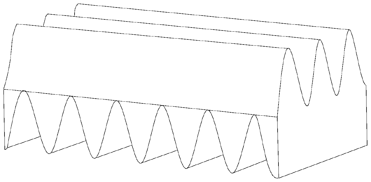
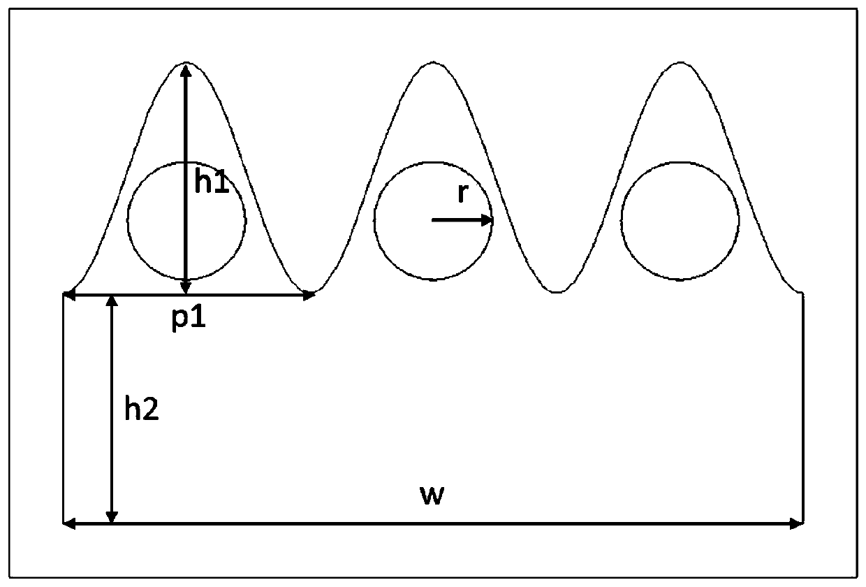
[0036] Such as Figure 1-Figure 3 As shown, a multi-electron injection channel slow-wave structure with a trigonometric function profile includes a rectangular housing 1, a plurality of sinusoidal gratings 4 distributed in the lower part of the rectangular housing 1, and two adjacent sinusoidal gratings 4 The room is a high-frequency system, the rectangular housing 1 has a plurality of cosine grating teeth 2 distributed above, and an electron beam channel is formed between two adjacent cosine grid teeth 2, and a circular electron beam 3 is arranged in the electron beam channel, so The sine grid teeth 4 and the cosine grid teeth 2 are orthogonal to each other; the edge profile shapes of the multiple cosine grid teeth 2 are distributed in a cosine function; the edge profile shapes of the multiple sine grid teeth 4 are distributed in a sine function; the outermost electron injection channel A certain point on the edge is the origin, the extension direction of the circular electro...


PUM


Abstract

The invention discloses a multi-electron-beam-channel slow-wave structure with a trigonometric function contour, and belongs to the technical field of electric vacuum devices. The structure is composed of a cuboid shell, a plurality of cosine grid teeth distributed at the upper part in the shell and a plurality of sine grid teeth distributed at the lower part in the shell, wherein an electron beamchannel is formed between every two adjacent cosine grid teeth, circular electron beams are arranged in the electron beam channels, and the part between two adjacent sine grid teeth serves as a high-frequency system so as to jointly form the multi-electron-beam-channel slow-wave structure. The multi-electron-beam-channel slow-wave structure with the trigonometric function contour provided by theinvention is suitable for working in high-order space harmonics, and can meet requirements of the terahertz wave band. Meanwhile, the structure is provided with the natural circular electron beam channels, can achieve long-distance transmission under the condition that the electron beam current density is not reduced, and can effectively conduct beam-wave interaction.

Description

technical field [0001] The invention relates to the technical field of microwave electric vacuum devices, in particular to a multi-electron injection channel slow-wave structure with a trigonometric function profile. Background technique [0002] A microwave vacuum device is a device that uses charged particles to oscillate or amplify microwave signals in a vacuum environment. The new generation of electric vacuum devices not only require high frequency, high power, and high efficiency, but also require high reliability, simple and easy processing, etc., in order to be able to meet new application requirements and challenges. [0003] The rapid development of solid-state devices and the urgent needs of aerospace and military fields have brought challenges and opportunities to electric vacuum devices. Traveling wave tubes are moving towards the terahertz frequency band. Terahertz wave refers to an electromagnetic wave with a frequency from 0.1 to 10.0 THz, that is, a wavele...

Claims


Application Information

Patent Timeline
Patent Type & Authority Applications(China)
IPC IPC(8): H01J23/24
CPCH01J23/24
Inventor 温瑞东路志刚朱美玲丁科森
Owner UNIV OF ELECTRONICS SCI & TECH OF CHINA
Why Eureka
Try Eureka