Pressing rivet screw automatic feeding device and system

An automatic feeding and screw technology, applied in metal processing, metal processing equipment, manufacturing tools, etc., can solve the problems of high processing difficulty, low efficiency, uneven production level, etc., achieve automation and mechanization, improve work efficiency, well-designed effects

Pending Publication Date: 2020-02-07
江苏普莱斯特精密技术有限公司
View PDF0 Cites 6 Cited by
  • Summary
  • Abstract
  • Description
  • Claims
  • Application Information

AI Technical Summary

Problems solved by technology

At present, in the field of riveting, with the continuous improvement of automation technology, the original working method of manually placing pressure riveting screws is gradually replaced by automation due to its high fatigue strength and low efficiency.
However, due to the uneven production level in the market, it is often blindly designed in order to realize automatic feeding, which generally has the problems of complex structure, high processing difficulty, serious waste of materials and low efficiency.

Method used


Image

  • Pressing rivet screw automatic feeding device and system
  • Pressing rivet screw automatic feeding device and system
  • Pressing rivet screw automatic feeding device and system

Examples


Embodiment 1

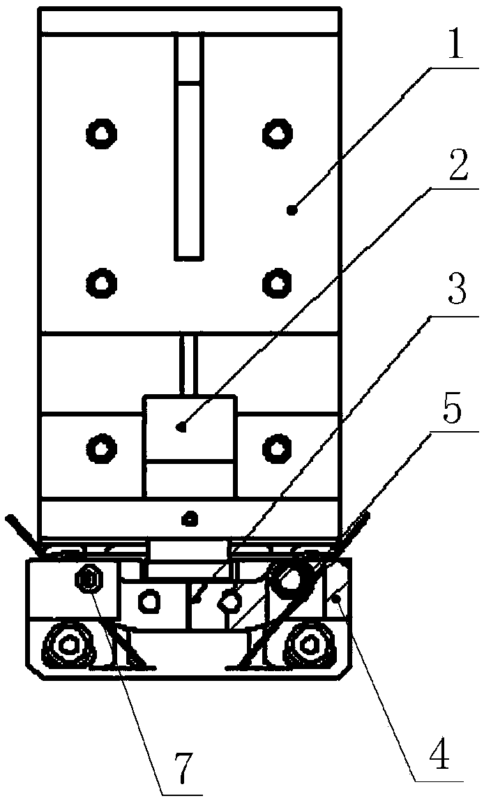
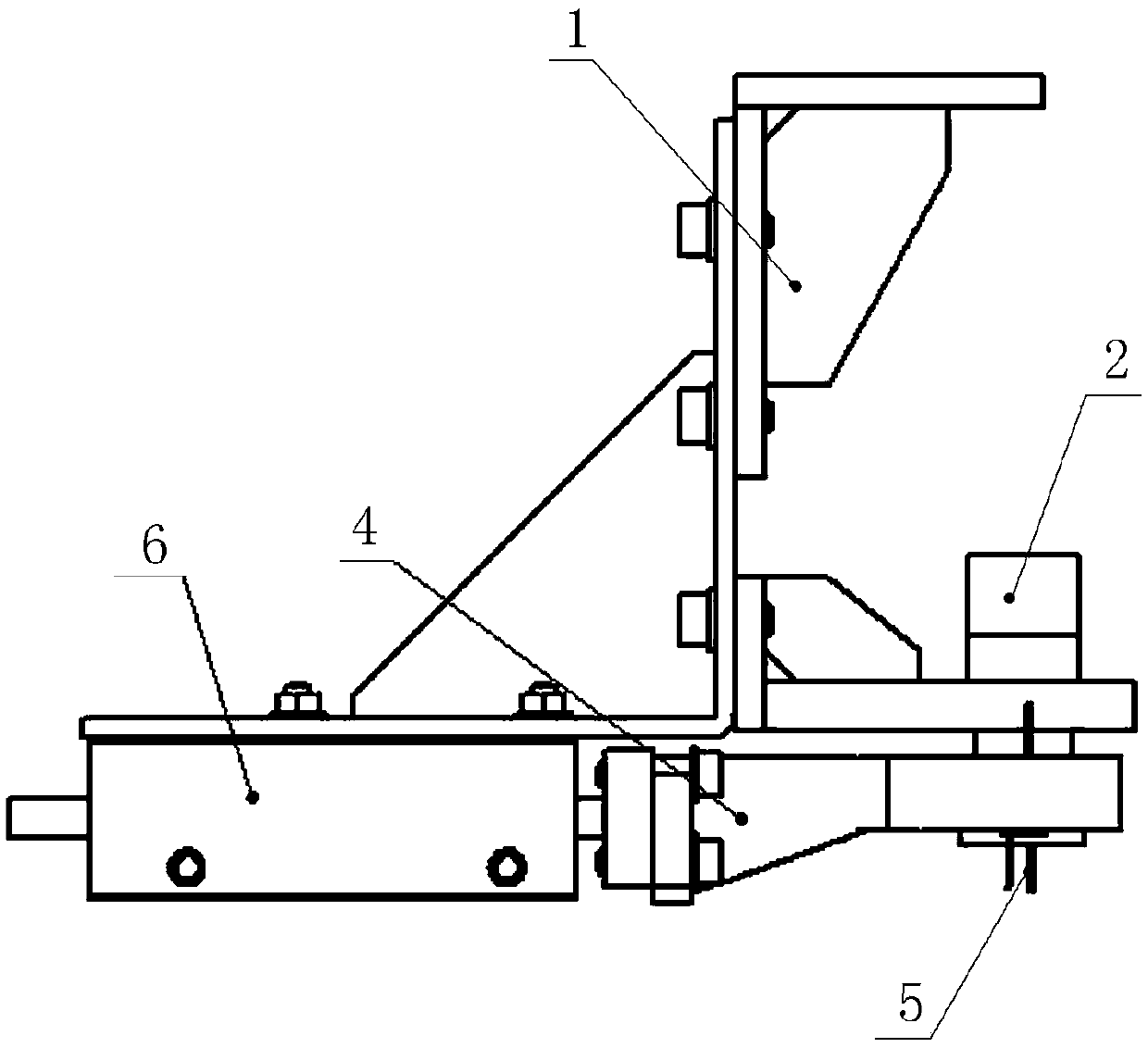
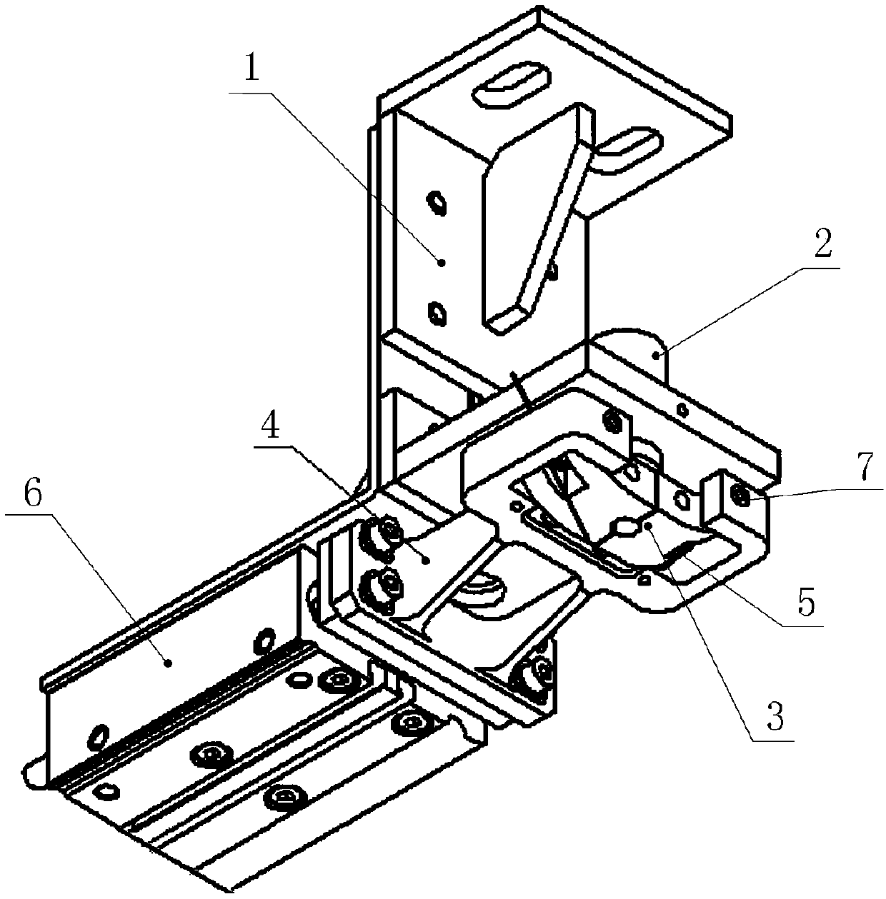
[0024] like Figure 1 ~ Figure 3 As shown, Embodiment 1 discloses an automatic feeding device for pressure riveting screws, which is mainly composed of a mounting bracket 1, a material tube seat 2, a flap 3, a flap bracket 4, a torsion spring 5 and a pushing cylinder 6.

[0025] The material pipe seat 2 is installed on the mounting bracket 1, and the material pipe seat 2 is provided with a material guide hole 2a penetrating from the top surface to the bottom surface; the pushing cylinder 6 is fixedly installed on the bottom of the mounting bracket 1, and the pushing cylinder 6 The piston rod end of the piston rod is forwardly connected with the flap bracket 4, and the telescopic piston rod of the pushing cylinder 6 drives the flap bracket 4 to move forward and backward, and switches between the feeding station and the riveting station.

[0026] The front portion of the flap support 4 is provided with a feed port, and when the flap support 4 is located at the feeding station, t...

Embodiment 2

[0030] like Figure 4 As shown, Embodiment 2 discloses an automatic feeding system for pressure riveting screws, which mainly consists of a pressure riveting frame 9, an upper mold 10, a pressure riveting cylinder 11, a lower mold 12, a lower mold base 13, a nail feeding unit, The vibrating plate support 14, the automatic feeding device for riveting screws and the supporting electric control box are composed, wherein the automatic feeding device for riveting screws adopts the automatic feeding device for riveting screws in Embodiment 1.

[0031] like Figure 4 As shown, the riveting frame 9 is provided with a riveting operation position; the upper part of the riveting operation position is provided with an upper die 10, and the upper die 10 is connected with the piston rod end of the riveting booster cylinder 11; The lower part of the pressure riveting operation position is provided with a lower mold 12 corresponding to the upper mold 10, and the lower mold 12 is installed on...


PUM


Abstract

The invention relates to a pressing rivet screw automatic feeding device. A material pipe seat is mounted on a mounting bracket, and a material guiding hole penetrating through the top surface to thebottom surface is formed in the material pipe seat; a material pushing cylinder is fixedly mounted at the bottom of the mounting bracket, the piston rod end of the material pushing cylinder is forwards connected with a flip plate bracket, and a piston rod of the material pushing cylinder extends and contracts to drive the flip plate bracket to move forwards and backwards and switch between a feeding station and a pressing rivet station; a feeding port is formed in the front part of the flip plate bracket, and when the flip plate bracket is located at the feeding station, the feeding port communicates with the lower end of the material guiding hole; and two symmetrically arranged flip plates are mounted in the feeding port, the flip plates are hinged to the two sides of the feeding port, and elastic reset pieces are arranged on the flip plates and the flip plate bracket. The invention further relates to a pressing rivet screw automatic feeding system. The pressing rivet screw automaticfeeding system comprises a pressing rivet machine frame and an electric control box, a pressing rivet operation position is arranged on the pressing rivet machine frame, and the pressing rivet screw automatic feeding device is mounted in the pressing rivet operation position. According to the pressing rivet screw automatic feeding device and system, automatic conveying of pressing rivet screws canbe realized, the working efficiency is improved, and the labor cost is saved.

Description

technical field [0001] The invention relates to an automatic feeding device and an automatic feeding system for pressure riveting screws, belonging to the technical field of pressure riveting automation. Background technique [0002] The pressure rivet screw is a commonly used riveting device, and its working principle is to embed the teeth on the pressure rivet screw into the plate. At present, in the field of riveting, with the continuous improvement of automation technology, the original working method of manually placing pressure riveting screws is gradually replaced by automation because of its high fatigue strength and low efficiency. However, due to the uneven production level in the market, it is often blindly designed in order to realize automatic feeding, which generally has the problems of complex structure, high processing difficulty, serious waste of materials and low efficiency. Therefore, it is of great significance to develop a structure with simple producti...

Claims


Application Information

Patent Timeline
Patent Type & Authority Applications(China)
IPC IPC(8): B23P19/00
CPCB23P19/001
Inventor 潘成超
Owner 江苏普莱斯特精密技术有限公司
Why Eureka
Try Eureka