Workpiece reversing device and workpiece placing equipment provided with same

A technology of reversing device and workpiece, applied in the direction of conveyor objects, transportation and packaging, etc., can solve the problems of long time, reduce product quality, and fail to meet the requirements of production capacity, so as to avoid quality degradation, overcome wear and improve production capacity. Effect

Pending Publication Date: 2020-02-07
上海康德莱医疗器械自动化研究所有限公司
View PDF0 Cites 2 Cited by
  • Summary
  • Abstract
  • Description
  • Claims
  • Application Information

AI Technical Summary

Problems solved by technology

[0002] In the process of workpiece processing, it is usually necessary to place the workpiece according to certain rules and order before the parts are transported to the processing station. The material box is piled up together, so during the conveying process, the conveying direction of the workpiece may not meet the swinging material standard. Therefore, it is necessary to carry out the workpieces that do not meet the swinging direction standard before being transported to the storage tray. Adjustment. At present, the following methods are mostly used for workpiece reversing: 1. Set up a clamping device during the conveying process of the workpiece, and adjust the direction of the workpiece by clamping and steering. Because the clamping device needs to firmly fix the workpiece Clamping will use a lot of force to wear the surface of the workpiece to a certain extent and reduce product quality; 2. During the transportation process, the direction of the workpiece that does not meet the requirements of the swing is manually adjusted, and the manual adjustment method is adopted. When there are many materials placed, it takes a long time and does not meet the requirements of production capacity

Method used


Image

  • Workpiece reversing device and workpiece placing equipment provided with same
  • Workpiece reversing device and workpiece placing equipment provided with same
  • Workpiece reversing device and workpiece placing equipment provided with same

Examples


Embodiment

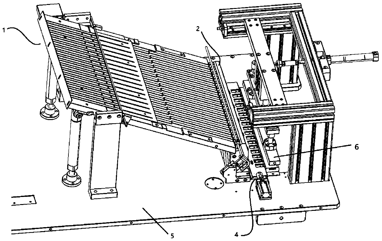
[0047] This embodiment provides a workpiece pendulum device, such as figure 1 As shown, the workpiece swinging equipment includes a base 5 and a workpiece feeding device, a workpiece reversing device and a workpiece retrieving device 6 arranged on the base 5. The workpiece feeding device includes several feeding troughs, and the workpiece is transported to the workpiece in the feeding chute. In the reversing device, the reversing is performed in the reversing device and continues to be transported to the storage tray. The workpiece retrieving device 6 includes a retrieving arm 61, and the workpiece is taken out from the retrieving tray by using the retrieving arm 61. Workpiece placement sequence The workpieces are placed in the swing tray, so that the output workpieces meet the requirements of the swing direction and are smoothly transported to the next station.

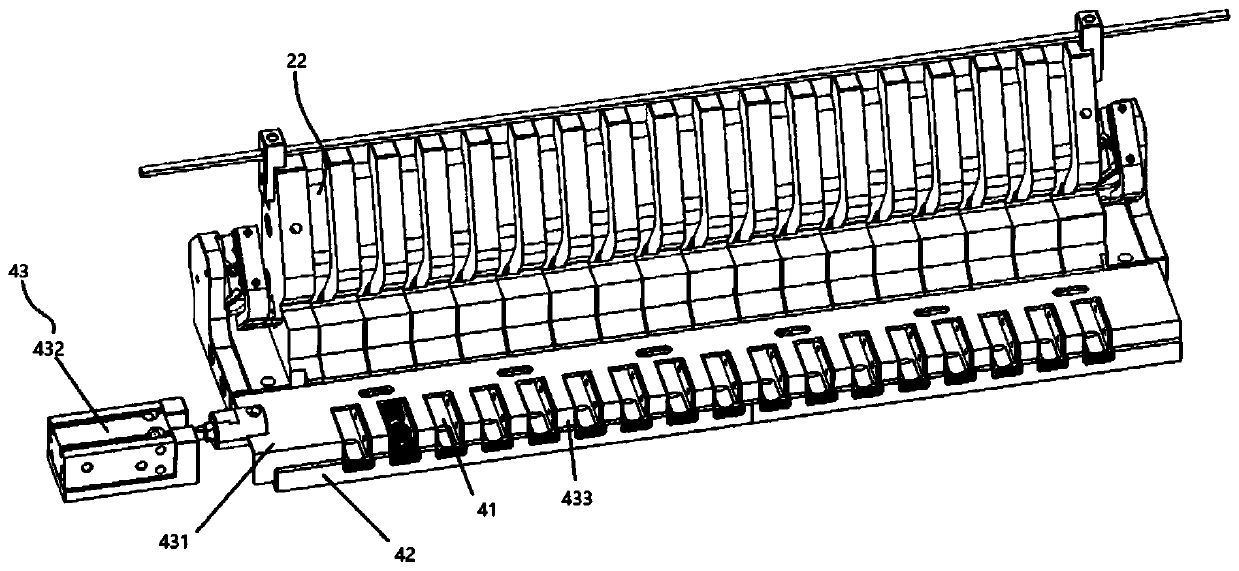
[0048] Such as figure 1 and figure 2 As shown, the workpiece reversing device in this embodiment is now describ...


PUM


Abstract

The invention discloses a workpiece reversing device and workpiece placing equipment provided with the same. The workpiece reversing device comprises a transmission unit for conveying a workpiece andan outputting mechanism, wherein the outputting mechanism is arranged on the transmission unit and comprises a plurality of outputting channels and reversing units arranged on the paths of the outputting channels; and the reversing units adjust the workpiece outputting direction. The outputting mechanisms are arranged on the transmission unit; when the workpieces are conveyed on the outputting channels, the reversing units adjust the direction during the conveying process, and conveying of the workpieces in the outputting channels is not delayed at the same time, so that the defect that the surface of the workpiece is worn when an external clamping device clamps the workpiece is overcome, and the situation that the workpiece quality is reduced due to clamping is avoided; and the reversingunits are arranged on the conveying paths of the outputting channels to avoid manual direction adjustment of the workpiece and increase the productivity of the workpiece.

Description

technical field [0001] The invention relates to the technical field of workpiece conveying, in particular to a workpiece reversing device and workpiece swinging equipment with the device. Background technique [0002] In the process of workpiece processing, it is usually necessary to place the workpiece according to certain rules and order before the parts are transported to the processing station. The material box is piled up together, so during the conveying process, the conveying direction of the workpiece may not meet the swinging material standard. Therefore, it is necessary to carry out the workpieces that do not meet the swinging direction standard before being transported to the storage tray. Adjustment. At present, the following methods are mostly used for workpiece reversing: 1. Set up a clamping device during the conveying process of the workpiece, and adjust the direction of the workpiece by clamping and steering. Because the clamping device needs to firmly fix t...

Claims


Application Information

Patent Timeline
Patent Type & Authority Applications(China)
IPC IPC(8): B65G47/248B65G47/26B65G47/88
CPCB65G47/248B65G47/26B65G47/8815
Inventor 不公告发明人
Owner 上海康德莱医疗器械自动化研究所有限公司
Why Eureka
Try Eureka