Conducting wire fixing device and manufacturing method

A wire fixing and manufacturing method technology, applied in the direction of line/collector parts, electrical components, circuits, etc., can solve problems such as high requirements for operators or equipment, poor reliability, and reduced connection reliability, so as to improve fixing efficiency, The effect of high fixed efficiency and reduced requirements

Pending Publication Date: 2020-02-07
慈溪天坤塑料制品有限公司
View PDF0 Cites 0 Cited by
  • Summary
  • Abstract
  • Description
  • Claims
  • Application Information

AI Technical Summary

Problems solved by technology

[0003] 1. The connection efficiency is low; the wire needs to be initially fixed on the circuit board, such as using tweezers to press to the welding place, and then finally fixed by welding;
[0004] 2. The reliability is poor; the wire is fixed on the circuit board by welding, and the probability of false welding is relatively high, which reduces the reliability of the connection;
[0005] 3. High requirements for operators or equipment; it is necessary to accurately press the wires to the welding place, and then weld and fix them. There are high requirements for the eyesight and operation accuracy of the operators. Novices need a long time of training and practical training to be able to Meet the requirements

Method used


Image

  • Conducting wire fixing device and manufacturing method
  • Conducting wire fixing device and manufacturing method
  • Conducting wire fixing device and manufacturing method

Examples


Embodiment 1

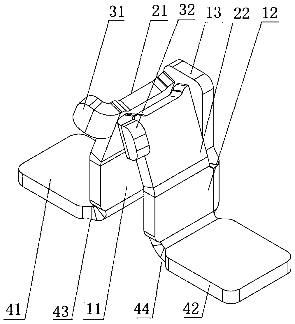
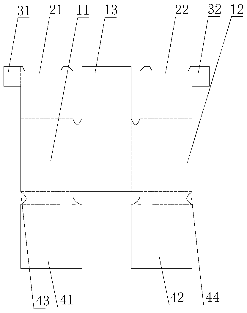
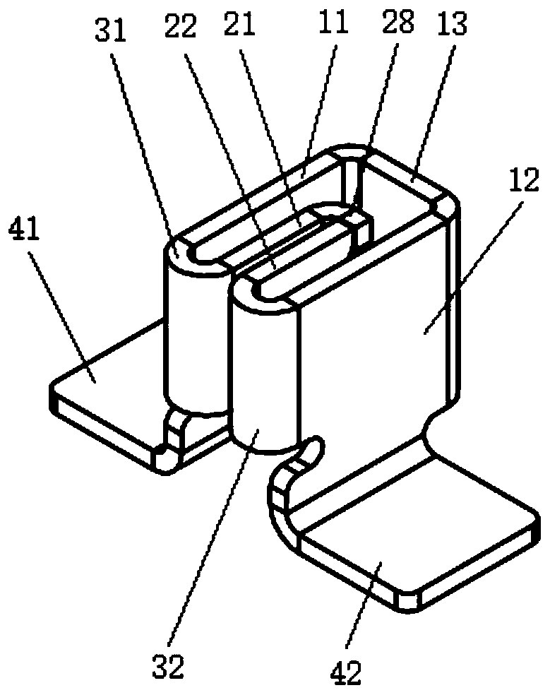
[0047] figure 1 Schematically provides a simplified structural diagram of the wire fixing device of the embodiment of the present invention, as figure 1 As shown, the wire fixing device includes:

[0048] Body 11-13, the opposite body is in the shape of "Π", the space formed is suitable for accommodating wires, and the side of the body has a first opening;

[0049] The clamping parts 21-22, the clamping parts 21-22 that are arranged oppositely are arranged on the side of the body, such as the upper side of the body, or the left and right sides, and the gap between the clamping parts 21-22 is not larger than that of the wire outer diameter; the side of the clamping portion has a second opening;

[0050] The guide part 31-32, from the outside to the inside, the width of the guide part 31-32 becomes smaller, which is convenient for guiding through the guide part to pass through the first opening and the second opening conveniently and quickly; the wire is suitable for passing t...

Embodiment 2

[0074] An application example of the wire fixing device according to Embodiment 1 of the present invention in a driving circuit.

[0075] In this application example, if figure 1 As shown, the lower sides of the first part 11 and the second part 12 of the body respectively have outwardly bent mounting parts 41-42, which are suitable for fixing such as welding on a circuit board; the upper sides of the first part 11 and the second part 12 are respectively It is the clamping part 21-22, and the upper end of the clamping part 21-22 that is arranged oppositely is inwardly concave, that is to say, the two sides are high, the middle is low, and the two clamping parts are all bent inwards, thereby forming a wire that is suitable for snapping in. The gap, and from bottom to top, the distance between the two clamping parts 21-22 gradually becomes smaller, and the gap is the smallest; the upper end position of the connecting part 13 is not lower than the position of the upper end of the...

Embodiment 3

[0090] The wire fixing device according to the embodiment of the present invention is different from Embodiment 2 in that:

[0091] There is no need to set the first opening, the clamping part and the guide part protrude outward relative to the main body; the connecting part only needs the lower part for connecting the first part and the second part, and no upper part is needed; the end of the clamping part away from the guide part is formed The width of the gap is less than 0.5 times the outer diameter of the wire, such as zero.


PUM


Abstract

The invention provides a conducting wire fixing device and a manufacturing method. The conducting wire fixing device comprises: a body and oppositely arranged body bearing and clamping portions; clamping portions, wherein the oppositely disposed clamping portions are disposed on side portions of the body, and the width of the gap between the clamping portions is not larger than the outer diameterof a conducting wire; and guide portions, wherein the distance between the oppositely disposed guide portions becomes smaller from outside to inside; and the conducting wire is suitable for passing through an area between the guide portions to be clamped in the gap. The conducting wire fixing device provided by the invention has the advantages of firm conducting wire fixing, high efficiency and the like.

Description

technical field [0001] The invention relates to wire fixing, in particular to a wire fixing device and a manufacturing method. Background technique [0002] At present, in the electrical connection between the wire and the circuit board, soldering is usually used. The disadvantages of this connection method are: [0003] 1. The connection efficiency is low; the wire needs to be initially fixed on the circuit board, such as using tweezers to press to the welding place, and then finally fixed by welding; [0004] 2. The reliability is poor; the wire is fixed on the circuit board by welding, and the probability of false welding is relatively high, which reduces the reliability of the connection; [0005] 3. High requirements for operators or equipment; it is necessary to accurately press the wires to the welding place, and then weld and fix them. There are high requirements for the eyesight and operation accuracy of the operators. Novices need a long time of training and prac...

Claims


Application Information

Patent Timeline
Patent Type & Authority Applications(China)
IPC IPC(8): H01R43/02
CPCH01R43/0249H01R43/0263
Inventor 王海卫符春华王桂东
Owner 慈溪天坤塑料制品有限公司
Why Eureka
Try Eureka