Rotor of permanent magnet motor, permanent magnet motor and compressor

A permanent magnet motor and rotor technology, applied in the direction of magnetic circuit rotating parts, magnetic circuit, electrical components, etc., can solve the problem of difficult saturation of permanent magnet magnetization, reduce harmonic content, improve air gap flux density waveform, Improve the effect of noise

Pending Publication Date: 2020-02-07
GUANGDONG MEIZHI COMPRESSOR
View PDF0 Cites 2 Cited by
  • Summary
  • Abstract
  • Description
  • Claims
  • Application Information

AI Technical Summary

Problems solved by technology

[0003] However, in the tangential flux structure, since one end of the permanent magnet protrudes into the vicinity of the inner hole of the rotor, it is difficult to saturate the magnetization after the permanent magnet is inserted into the rotor. This problem is one of the technical difficulties of the tangential flux structure motor

Method used


Image

  • Rotor of permanent magnet motor, permanent magnet motor and compressor
  • Rotor of permanent magnet motor, permanent magnet motor and compressor
  • Rotor of permanent magnet motor, permanent magnet motor and compressor

Examples


Embodiment

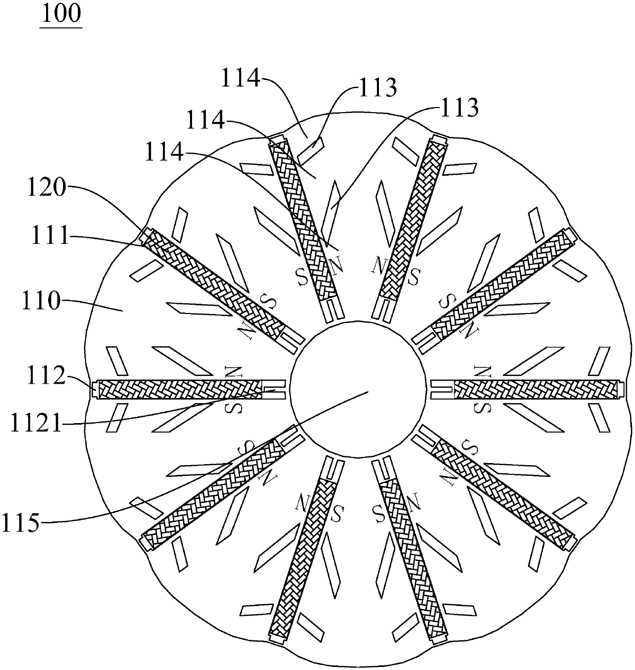
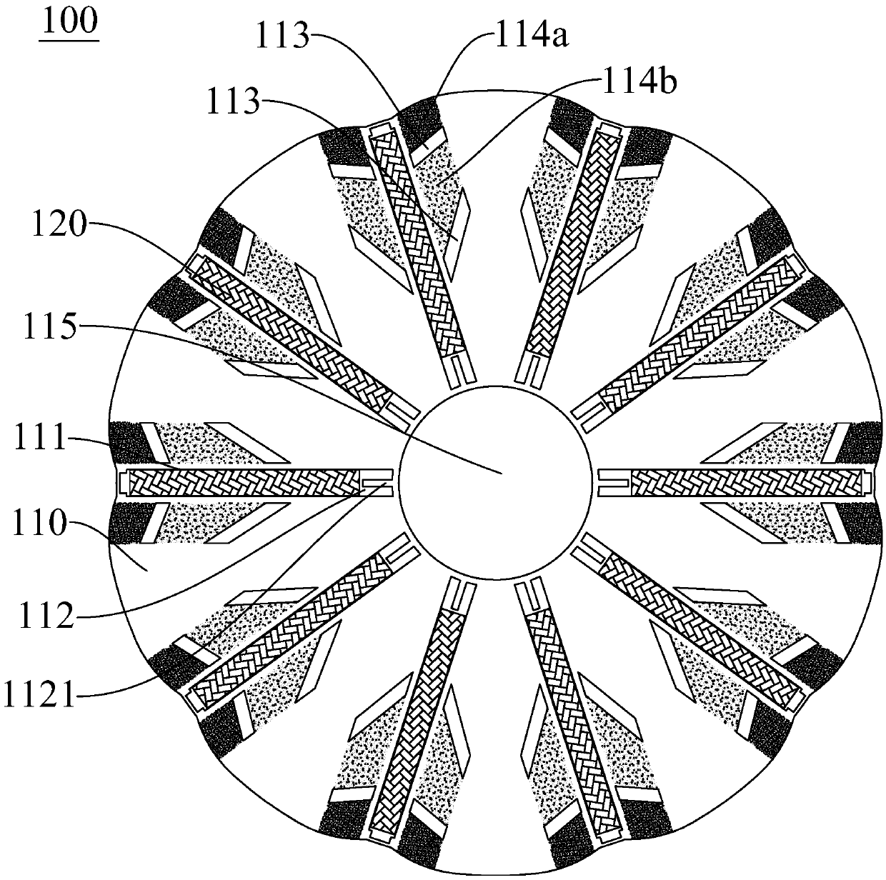
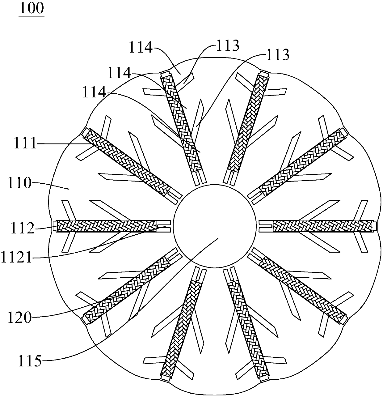
[0061] Refer below Figure 1-Figure 2 A rotor 100 of a permanent magnet motor according to a specific embodiment of the present invention is described.

[0062] Such as figure 1 As shown, the rotor 100 of the permanent magnet motor of this embodiment includes a rotor core 110 and ten permanent magnets 120, the rotor core 110 has a central hole 115 and ten magnet slots 111, and the ten magnet slots 111 are along the center hole 115. Circumferentially arranged, each magnet slot 111 extends along the radial direction of the central hole 115, and ten permanent magnets 120 are inserted in a plurality of magnet slots 111 one by one, and each magnet slot 111 is located in each permanent magnet Parts at both ends of the radial direction of 120 form first magnetic isolation slots 112 . The inner wall of the first magnetic separation slot 112 located radially inside the permanent magnet 120 facing the center of the rotor core 110 has an elongated protrusion 1121 protruding radially ou...


PUM


Abstract

The invention discloses a rotor of a permanent magnet motor, the permanent magnet motor and a compressor. The rotor includes a rotor iron core and a plurality of permanent magnets. The rotor iron coreis provided with a center hole and a plurality of magnet slots. The plurality of magnet slots are arranged in the circumferential direction of the center hole. Each of the magnet slots extends in theradial direction of the center hole. Portions, located at the two ends of each of the permanent magnets in the radial direction, of each of the magnet slots form first magnetic isolation slots. The rotor iron core is provided with a second magnetic isolation slot on at least one side of each of the magnet slots in the circumferential direction. Each second magnetic isolation slot separates a single-sided area where the second magnetic isolation slot is located into a plurality of magnetic field pathways distributed in the radial direction. In two magnetic field pathways adjacent in the radialdirection, the minimum width of the magnetic field pathway located on the outer side in the radial direction is smaller than the minimum width of the magnetic field pathway on the inner side in the radial direction. According to the permanent magnet motor of the embodiment of the invention, the magnetization characteristics of the rotor iron core are improved, and noises of the permanent magnet motor are reduced.

Description

technical field [0001] The invention relates to the field of compressors, in particular to a rotor of a permanent magnet motor, a permanent magnet motor and a compressor. Background technique [0002] The embedded permanent magnet motor is divided into two structures: radial flux and tangential flux according to the direction of flux. In the permanent magnet motor with tangential flux structure, the permanent magnets in the rotor extend along the radial direction of the rotor. For permanent magnet motors with a tangential flux structure, since the two working surfaces of the permanent magnets directly face the air gap, compared with the radial flux structure, the flux utilization rate is higher, which is more conducive to achieving high efficiency and miniaturization. [0003] However, in the tangential flux structure, since one end of the permanent magnet protrudes into the vicinity of the inner hole of the rotor, it is difficult to saturate the magnetization after the per...

Claims


Application Information

Patent Timeline
Patent Type & Authority Applications(China)
IPC IPC(8): H02K1/27
CPCH02K1/276
Inventor 乔正忠徐飞毛临书邱小华王玉龙
Owner GUANGDONG MEIZHI COMPRESSOR
Why Eureka
Try Eureka