Multifunctional dimming control circuit

A dimming control circuit and multi-functional technology, applied in the direction of electrical components, etc., can solve the problems affecting the energy-saving effect of LED power supply, reduce customer selection, changeable application requirements, etc., achieve simple structure, improve energy-saving effect, and fewer components Effect

Pending Publication Date: 2020-02-07
四川力士达智慧照明科技有限公司
View PDF0 Cites 1 Cited by
  • Summary
  • Abstract
  • Description
  • Claims
  • Application Information

AI Technical Summary

Problems solved by technology

[0004] The purpose of the present invention is to provide a multifunctional dimming control circuit, which solves the problem that the current LED power supply dimming is a single dimming method, and users will encounter many problems during use, and must purchase a matching The dimming controller is very inconvenient and cannot meet the changing application requirements, thereby reducing the selection of customers and affecting the energy-saving effect of LED power supplies.

Method used


Image

  • Multifunctional dimming control circuit
  • Multifunctional dimming control circuit

Examples


Embodiment 1

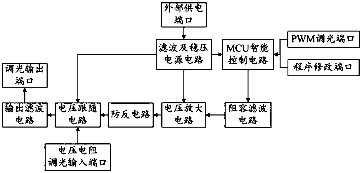
[0033] A multifunctional dimming control circuit, such as figure 1 The multifunctional dimming control circuit mainly includes MCU intelligent control circuit, PWM dimming port, voltage resistance dimming input port, program modification port, resistance-capacitance filter circuit, filter and regulated power supply circuit, voltage amplifier circuit, anti-reverse circuit, voltage follower circuit, output filter circuit and dimming output port;

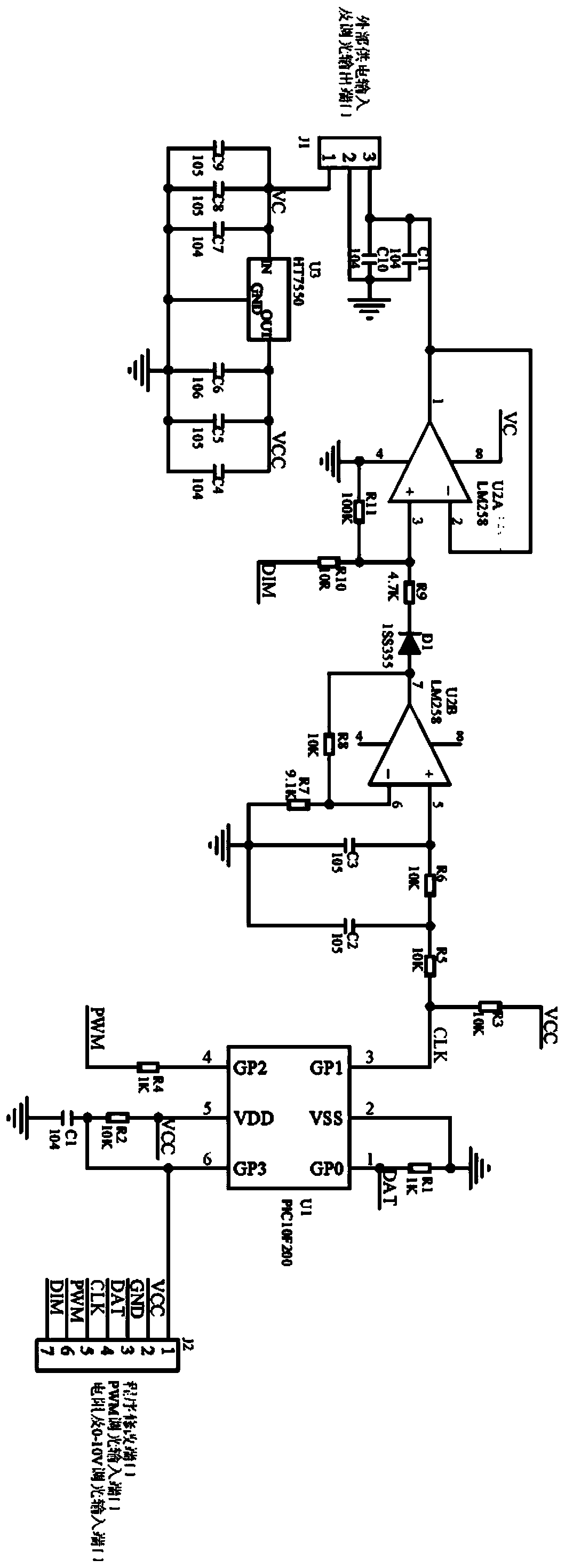
[0034] The program modification port and the PWM dimming port are unidirectionally connected to the microcontroller U1 of the MCU intelligent control circuit, such as figure 2 , here the single chip U1 we choose PIC10F200 single chip microcomputer, the external power supply port generates a stable DC voltage after filtering and stabilized power supply circuit, the filtering and stabilized power supply circuit are unidirectionally connected to the MCU intelligent control circuit and voltage amplifier circuit. and a voltage follower ci...

Embodiment 2

[0037] This embodiment is a further description of Embodiment 1, such as figure 2 , the filtering and stabilizing power supply circuit mainly includes, the external power supply input VC is connected to the IN port of the voltage stabilizer U3, the IN port of the voltage stabilizer U3 is grounded through the parallel capacitors C7, C8, and C9, and the The OUT port of the voltage stabilizer U3 is grounded through parallel capacitors C4, C5 and C6, the GND port of the voltage stabilizer U3 is grounded, and the voltage output by the OUT port of the voltage stabilizer U3 is the VCC power supply voltage of the control circuit.

[0038] Here, we use HT7550 type regulator for voltage regulator U3, and the size of capacitors C4, C5, C6, C7, C8, and C9 are 10 4 pF, 10 5 pF, 10 6 pF, 10 4 pF, 10 5 pF, 10 5 pF.

[0039] According to the actual needs, the filtering and voltage stabilization circuit we designed here uses the voltage stabilizer U3. The IN port of the voltage stabiliz...

Embodiment 3

[0041] This embodiment is a further description of Embodiment 1. The program modification port and the PWM dimming port are respectively unidirectionally connected to the single-chip microcomputer U1 of the MCU intelligent control circuit, and the connection modes mainly include, the program modification port includes four ports, They are respectively connected to the VDD pin, GP3 pin, GP0 pin and GP1 pin of the microcontroller U1, and the PWM dimming port is connected to the GP2 pin of the microcontroller U1 through the 1KΩ resistor R4.

[0042] The program modification port and the PWM dimming port respectively adjust the input of the single-chip microcomputer U1 of the MCU intelligent control circuit. Generally speaking, one of them is selected according to the actual needs. When using the program modification port to modify the internal program of the single-chip microcomputer U1, the time and the corresponding value can be set. Voltage output, so that different voltages ca...


PUM


Abstract

The invention discloses a multifunctional dimming control circuit, and relates to the field of LED lighting power supply driving control. The electric power structure mainly comprises a program modification port and a PWM dimming port, which are unidirectionally connected to a single-chip microcomputer of an MCU intelligent control circuit. An external power supply port generates a stable direct-current voltage to supply power to the whole circuit through a filtering and voltage-stabilizing power supply circuit. The MCU intelligent control circuit is sequentially connected to a resistance-capacitance filter circuit, a voltage amplification circuit, an anti-reverse circuit, a voltage follower circuit and an output filter circuit in a one-way mode. The output filter circuit is connected to adimming output port in a one-way mode; and a voltage resistance dimming input port is connected to the voltage follower circuit in a one-way mode. According to the circuit, PWM dimming, timing dimming and voltage and resistance dimming can be selected and used according to actual requirements, and variable application requirements of users can be met, so that the selection of customers is reduced, and the energy-saving effect of an LED power supply is improved; and the circuit can adapt to different application scenes, and the application range is greatly expanded.

Description

technical field [0001] The invention relates to the field of LED lighting power drive control, in particular to a multifunctional dimming control circuit. Background technique [0002] At present, as the fourth-generation high-efficiency and green lighting source, LED is more and more widely used. LED has the advantages of high luminous efficiency, low energy consumption, long life, high CRI, color gamut light, easy control, small size, no mercury pollution, etc. , and the material is recyclable and has good controllability. In order to achieve a more comfortable and energy-saving lighting environment, the research on multi-functional LED dimming technology is imperative. At present, LED power dimming is a single dimming method. Users will encounter many problems in the process of use. They must purchase a matching dimming controller, which is very inconvenient and cannot meet the changing application needs. Thereby reducing the selection of customers and affecting the ener...

Claims


Application Information

Patent Timeline
Patent Type & Authority Applications(China)
IPC IPC(8): H05B45/30
Inventor 郑杨郑道昌杨红学王章科
Owner 四川力士达智慧照明科技有限公司
Why Eureka
Try Eureka