Heat dissipation structure and method for manufacturing same

A technology of heat dissipation structure and manufacturing method, applied in cooling/ventilation/heating transformation, components of pumping devices for elastic fluids, non-variable-capacity pumps, etc., can solve the problems of reduced efficiency, complex process, long time consumption, etc. , to achieve the effect of improving efficiency, simple process and reducing cost

Pending Publication Date: 2020-02-07
SZ DJI TECH CO LTD
View PDF8 Cites 0 Cited by
  • Summary
  • Abstract
  • Description
  • Claims
  • Application Information

AI Technical Summary

Problems solved by technology

This process has the following problems: due to the small size of the magnetic parts, it is inconvenient to manually place them into the groove of the mold, and it takes a long time, and if the magnetic parts are placed into the grooves using jigs or automated equipment, the magnetic parts are easy to be cured tools or automation equipment, it needs to be put in repeatedly, resulting in complicated process and low efficiency

Method used


Image

  • Heat dissipation structure and method for manufacturing same
  • Heat dissipation structure and method for manufacturing same
  • Heat dissipation structure and method for manufacturing same

Examples


Embodiment Construction

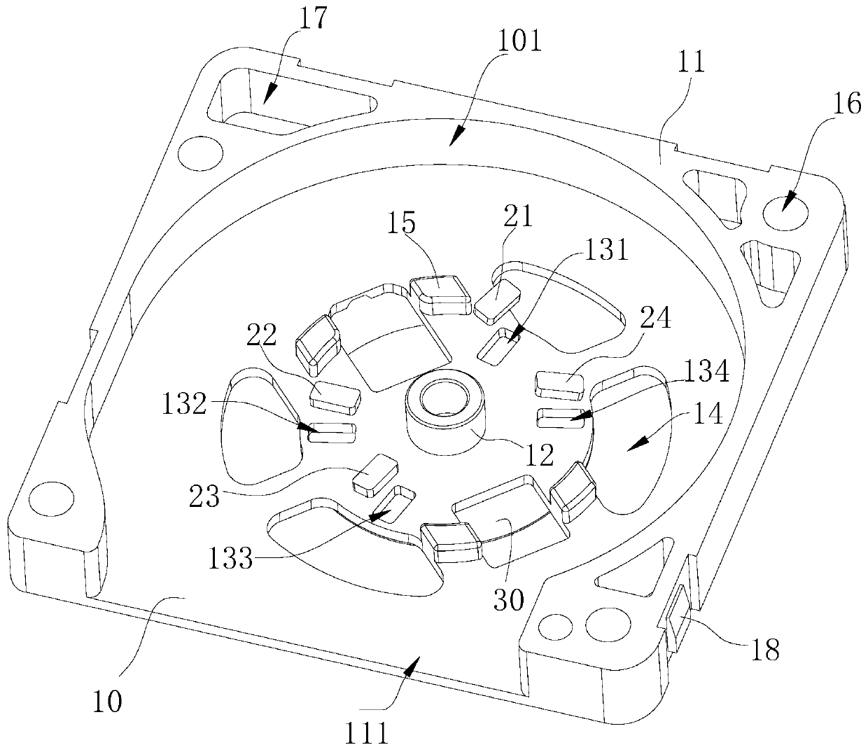
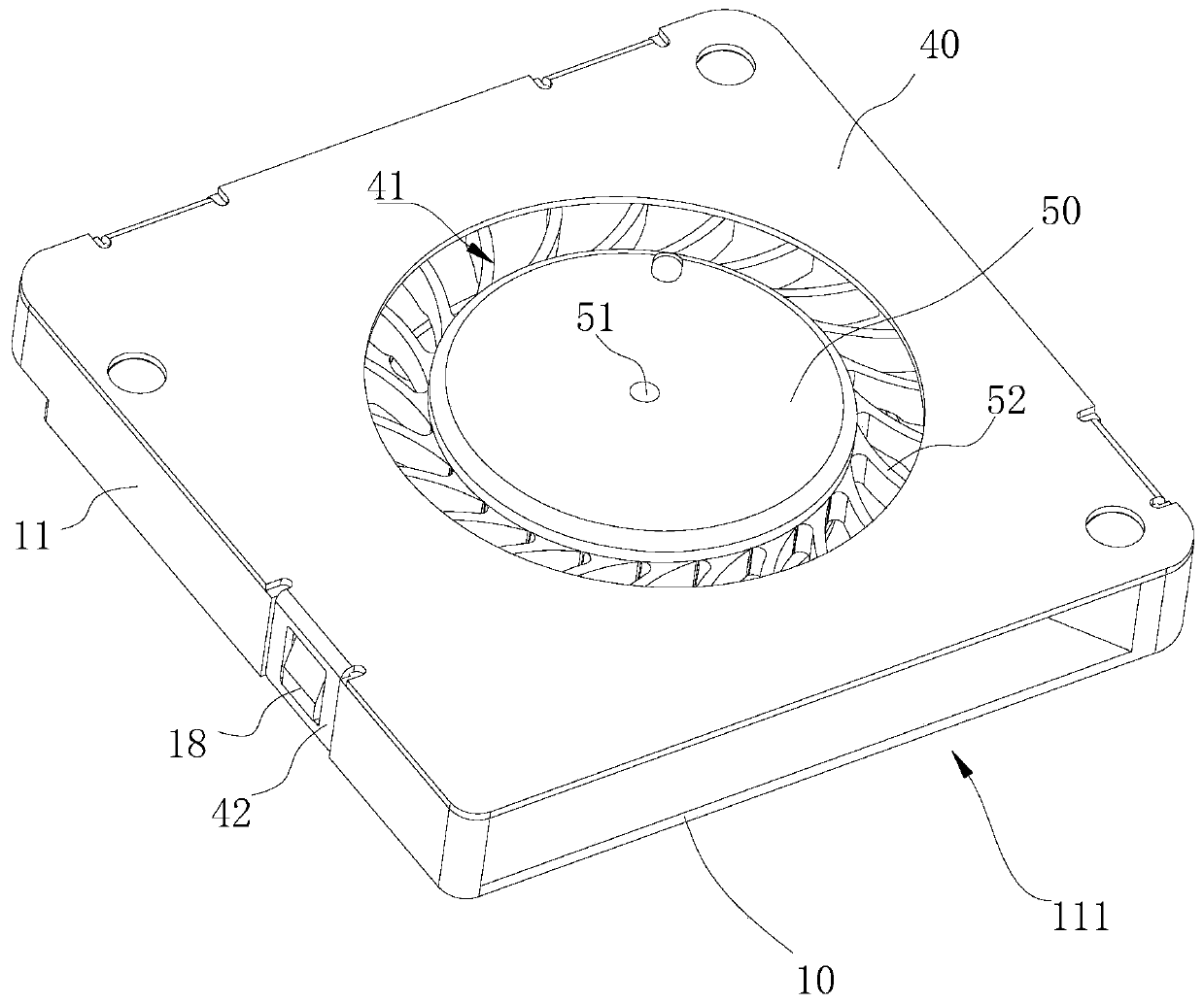
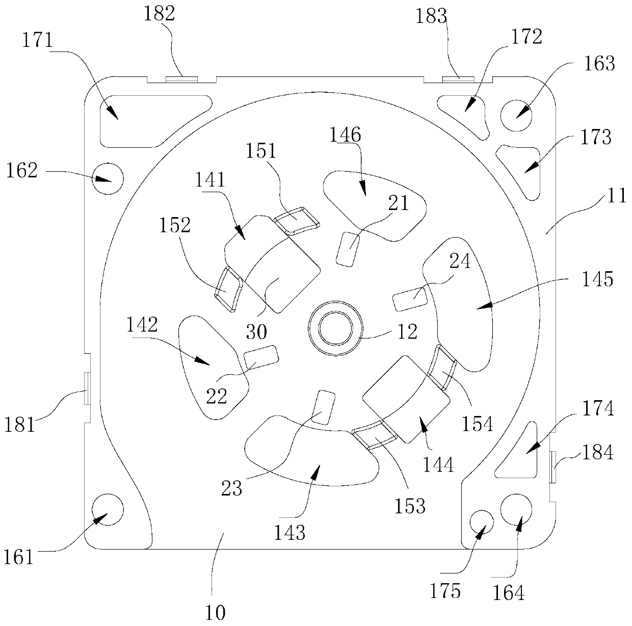
[0040] The technical solutions in the embodiments of the present invention will be clearly described below in conjunction with the accompanying drawings in the embodiments of the present invention. Obviously, the described embodiments are only some, not all, embodiments of the present invention. Based on the embodiments of the present invention, all other embodiments obtained by persons of ordinary skill in the art without making creative efforts belong to the protection scope of the present invention.

[0041] It should be noted that when a component is said to be "fixed" to another component, it can be directly on the other component or there can also be an intervening component. When a component is said to be "connected" to another component, it may be directly connected to the other component or there may be intervening components at the same time.

[0042] Unless otherwise defined, all technical and scientific terms used herein have the same meaning as commonly understood...


PUM


Abstract

The present application provides a heat dissipation structure and a method for manufacturing the same. The heat dissipation structure comprises a magnetic conductive member and a bottom plate. The bottom plate is provided with a shaft tube thereon, and is provided with a through-hole arranged around the shaft tube. The through-hole accommodates the magnetic conductive member. A sticker is attachedto a surface of the bottom plate facing away from the shaft tube. The sticker covers the through-hole, and the magnetic conductive member is attached and fixed to the sticker. In contrast to the prior art, when the bottom plate of the present application is manufactured, it is not required to integrate the magnetic conductive member into the bottom plate, thereby simplifying processes and improving efficiency. Moreover, a use of the sticker to fix the magnetic conductive member enables multiple functions of the sticker and reduces costs.

Description

technical field [0001] The present application relates to the technical field of heat dissipation, in particular to a heat dissipation structure and a method for manufacturing the heat dissipation structure. Background technique [0002] In the existing heat dissipation structure, a magnetic conductive member is often provided to limit the position of the rotor of the heat dissipation structure when it stops, so as to activate the rotor when starting. In the existing heat dissipation structure, the magnetic conductive part is usually made as a whole with the bottom plate of the heat dissipation structure. The process is usually to use a mold for one-time molding, that is, first set a groove for the magnetic conductive part on the mold, and put the magnetic conductive part into the In the groove, make the bottom plate again. This process has the following problems: due to the small size of the magnetic parts, it is inconvenient to manually place them into the groove of the m...

Claims


Application Information

Patent Timeline
Patent Type & Authority Applications(China)
IPC IPC(8): F04D25/08F04D29/00F04D29/62
CPCF04D25/08F04D29/002F04D29/626F04D29/00F04D29/62H05K7/20
Inventor 余强
Owner SZ DJI TECH CO LTD
Why Eureka
Try Eureka