Method for operating a brake system and brake system

A brake system and brake fluid technology, applied in the direction of brake control system, brake transmission device, brake action activation device, etc., can solve the problem of inaccurate pressure estimation, inability to calculate volume flow, pressure difference to calculate volume flow, etc. question

Pending Publication Date: 2020-02-11
ROBERT BOSCH GMBH
View PDF1 Cites 0 Cited by
  • Summary
  • Abstract
  • Description
  • Claims
  • Application Information

AI Technical Summary

Problems solved by technology

However, when the braking torque is blocked, the rear outlet valve of the brake system is permanently open, thereby directly compensating the pressure between the rear outlet valve and the storage chamber, so that the magnitude of the pressure difference is not sufficient bas...

Method used


Image

  • Method for operating a brake system and brake system
  • Method for operating a brake system and brake system

Examples


Embodiment Construction

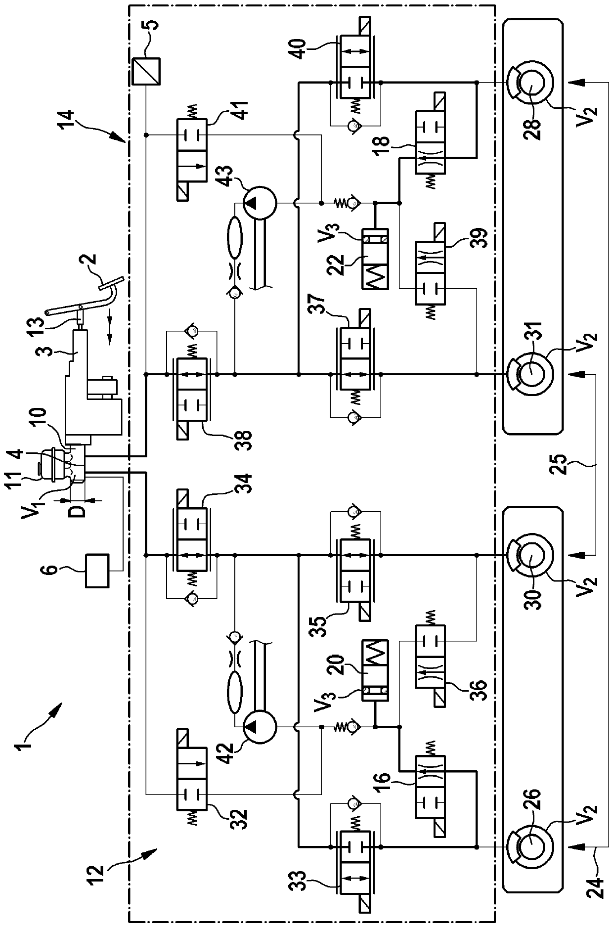
[0031] figure 1 A hydraulic circuit diagram of a brake system for a motor vehicle according to a preferred embodiment of the invention is shown.

[0032] Brake system 1 for a motor vehicle has a brake master cylinder 10 , a first brake circuit 12 connected to brake master cylinder 10 and a second brake circuit 14 connected to brake master cylinder 10 .

[0033] The brake system 1 also has a calculation unit 6 which is designed to calculate the amount of first brake fluid which is moved from the master brake cylinder 10 into the brake system 1 by the driver of the motor vehicle by actuating the brake pedal 2 . Volume V 1 , see formula (1).

[0034] (s(output rod)-s(compensation joint closed)) Equation (1).

[0035] D is the diameter of the master brake cylinder 10, s (output rod) is the movement stroke of the output rod 3 of the brake system 1 connected to the brake pedal 2, and s (compensation joint closed) is the The movement stroke of the output rod 3 of the compensati...


PUM


Abstract

The invention relates to a method for operating a brake system. The method comprises: calculating (S1) a first brake fluid volume (V1) displaced by a driver of the motor vehicle by actuating a brake pedal (2) from a master brake cylinder (10) into a brake system (1), calculating (S2) a second brake fluid volume (V2) in wheel brake cylinders (26 , 28, 30, 31) of the brake system (1), and calculating (S3) a third brake fluid volume (V3) in at least one storage chamber (20, 22) of the brake system (1) by using the calculated one first brake fluid volume (V1) and the calculated second brake fluidvolume (V2). The invention further relates to a brake system (1) for a motor vehicle.

Description

technical field [0001] The invention relates to a method for operating a brake system for a motor vehicle. The invention also relates to a braking system for a motor vehicle. Background technique [0002] A common method used to operate a brake system may include estimating or determining the volume of brake fluid in a reservoir chamber of the brake system. [0003] In the braking systems of electrically operated vehicles and hybrid vehicles, the braking power is provided both by a regenerative braking torque generated by the electric machine and by a hydraulic braking torque generated by the braking system. [0004] In different driving situations, the regenerative braking torque and the hydraulically generated braking torque can be shielded in order to obtain a constant braking power even in regenerative operation of the motor vehicle. [0005] In the context of purely regenerative braking, a volume of brake fluid is displaced into at least one storage chamber of the bra...

Claims


Application Information

Patent Timeline
IPC IPC(8): B60T13/66B60T8/171
CPCB60T13/66B60T8/171B60T2220/04B60T2270/604B60T7/042B60T13/662B60T13/686B60T13/146
Inventor 长仓安孝
Owner ROBERT BOSCH GMBH
Why Eureka
Try Eureka