
High-rise building aviation warning light based on reversible reaction principle

A high-rise building and warning light technology, applied in the field of construction, can solve the problems of aviation warning light glare, solar panels are difficult to maintain, etc., and achieve the effect of ensuring the warning effect

Active Publication Date: 2020-02-11
绍兴盛坤机械科技有限公司
View PDF5 Cites 3 Cited by
  • Summary
  • Abstract
  • Description
  • Claims
  • Application Information

AI Technical Summary

Problems solved by technology

[0005] The object of the present invention is to provide an aviation warning light for high-rise buildings that avoids glare and can protect solar panels based on the principle of reversible reaction for the above-mentioned aviation warning lights that easily cause glare and solar panels are difficult to maintain.

Method used


Image

  • High-rise building aviation warning light based on reversible reaction principle
  • High-rise building aviation warning light based on reversible reaction principle
  • High-rise building aviation warning light based on reversible reaction principle

Examples


Embodiment 1

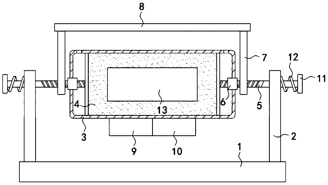
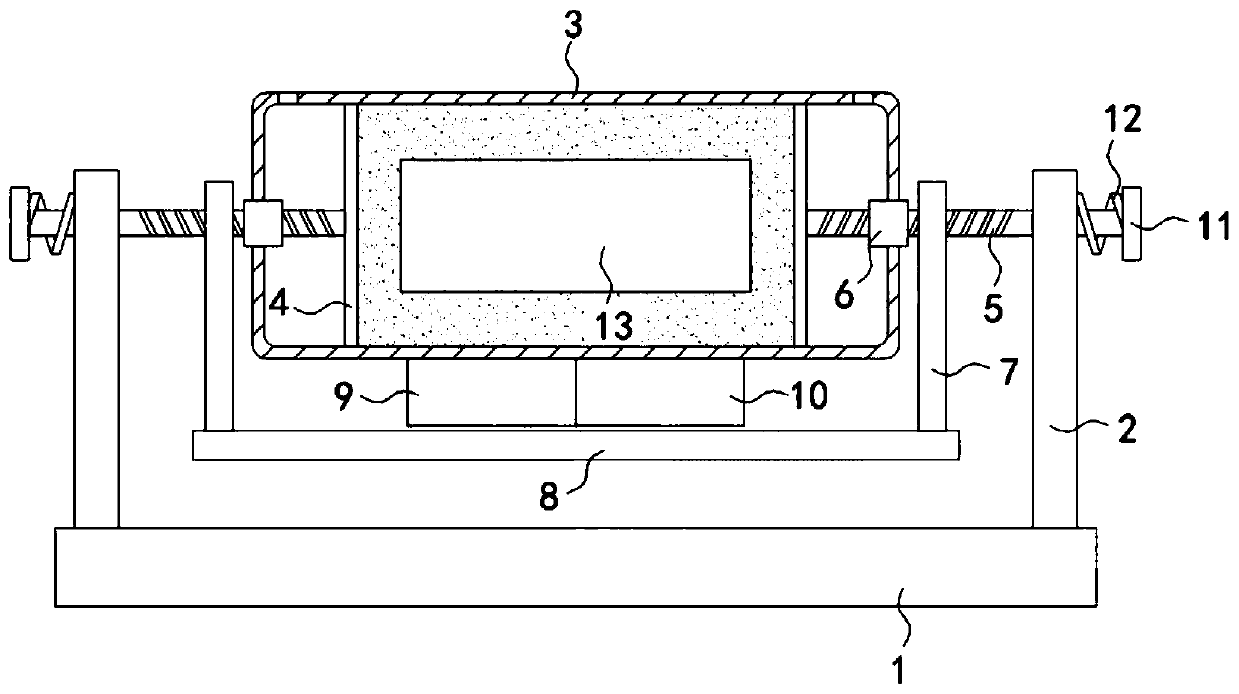
[0024] Such as Figure 1-2 As shown, an aviation warning light for high-rise buildings based on the principle of reversible reaction includes a mounting base 1 fixedly installed on the top of the high-rise building. The upper surface of the mounting base 1 is fixedly connected with two support plates 2. There is a housing 3, the housing 3 is made of a transparent material, the housing 3 is provided with an LED light source 13, two sealing plates 4 are sealed and slidably connected to the inner wall of the housing 3, and the space between the two sealing plates 4 is filled with Equilibrium mixed gas of nitrogen dioxide and dinitrogen tetroxide.

[0025] In this embodiment, the ends of the two sealing plates 4 that are far away from each other are rotatably connected with threaded rods 5, and the other ends of the threaded rods pass through the housing 3 and the support plate 2 in sequence and are movably connected with the support plate 2. It should be noted that the threads T...

Embodiment 2

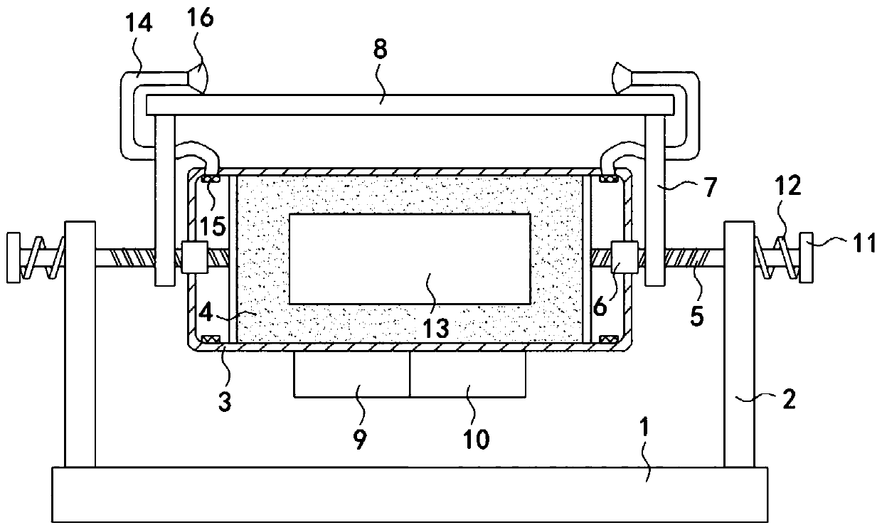
[0031] Such as Figure 3-4 As shown, the difference between this embodiment and Embodiment 1 is that an annular sealing plate 15 is rotatably connected to the inner side wall of the housing 3, and an arc shape matched with the annular sealing plate 15 is provided on the side wall of the housing 3. Groove, connecting plate 7 is provided with a U-shaped tube 14 through, the upper end of the U-shaped tube 14 extends to the upper surface of the solar panel 8, the lower end of the U-shaped tube 14 runs through the annular sealing plate 15 and communicates with the housing 3, the solar panel 8 During the rotation, the lower end of the U-shaped tube 14 is driven to slide in the arc-shaped groove, and the annular sealing plate 15 rotates accordingly, ensuring the communication between the U-shaped tube 14 and the housing 3. It is worth mentioning that the U-shaped tube The upper end of 14 is fixedly connected with shower head 16, and shower head 16 is divergent shape setting, has expa...


PUM


Abstract

The invention belongs to the field of building and particularly relates to a high-rise building aviation warning light based on a reversible reaction principle. The warning light comprises a mountingbase which is fixedly mounted on the top of a high-rise building, wherein two supporting plates are fixedly connected with the upper surface of the mounting base; a shell is set above the mounting base; the shell is made of a transparent material; an LED light source is set in the shell; two sealing plates are in sealed slide connection with the inner side wall of the shell; an equilibrium state mixed gas of nitrogen dioxide and dinitrogen tetroxide is filled between the two sealing plates; and a threaded rod is rotationally connected with mutually distant ends of the two sealing plates. According to the warning light, light transmittance of the equilibrium state mixed gas of the nitrogen dioxide and the dinitrogen tetroxide in the shell is controlled according to the day and the night; eyesight of a pedestrian is prevented from being influenced by harsh glare which is emitted by the aviation warning light; moreover, a position of a solar panel can be adjusted; and maintenance frequency of the solar panel is effectively reduced.

Description

technical field [0001] The invention belongs to the construction field, in particular to an aviation warning light for high-rise buildings based on the principle of reversible reaction. Background technique [0002] Aviation warning lights are a kind of driving lights that can remove obstacles during aviation driving. Aviation warning lights can generally be divided into low-intensity aviation warning lights, medium-intensity aviation warning lights, high-intensity aviation warning lights, and the flashing frequency of aviation warning lights. Generally between 20 and 70 times per minute, according to national requirements, as long as the large high-rise buildings above 45 meters above the ground must be provided with aviation warning lights. [0003] Most of the existing aviation warning lights are powered by solar panels, but because the high-altitude environment is relatively harsh, it is not convenient to maintain and clean the solar panels, so the solar panels are easil...

Claims


Application Information

Patent Timeline
IPC IPC(8): F21S10/06F21S9/03F21V21/02F21V15/01F21V19/00F21V31/00F21V17/12F21V9/40B08B5/02F21Y115/10
CPCB08B5/02F21S9/035F21S10/06F21V15/01F21V17/12F21V19/001F21V21/02F21V31/005F21Y2115/10F21V9/40Y02B10/10
Inventor 黄倩倩
Owner 绍兴盛坤机械科技有限公司
Learn More