Track board deformation monitoring device and method and online monitoring system

A deformation monitoring and track plate technology, which is applied in measuring devices, optical devices, instruments, etc., can solve the problem that the displacement conversion method is not direct enough.

Pending Publication Date: 2020-02-11
CR TECHCAL DEV CORP +3
View PDF0 Cites 3 Cited by
  • Summary
  • Abstract
  • Description
  • Claims
  • Application Information

AI Technical Summary

Problems solved by technology

Combining the principle of distributed optical fiber sensing technology and the Pythagorean theorem to calculate the height of the isosceles triangle, so as to obtain the arch displacement on the track plate, that is, the vertical displacement. However, this monitoring method needs to use the isosceles triangle for conversion, so this displacement conversion The method is not direct enough

Method used


Image

  • Track board deformation monitoring device and method and online monitoring system
  • Track board deformation monitoring device and method and online monitoring system
  • Track board deformation monitoring device and method and online monitoring system

Examples


Embodiment 1

[0089] 1. Example 1 - Vertical deformation of the track plate

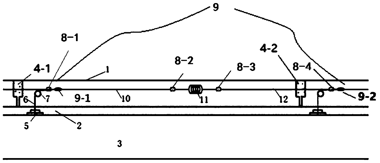
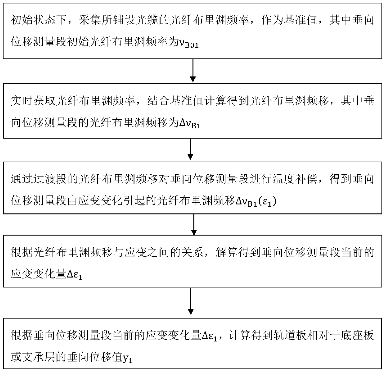
[0090] When the track board 1 is in continuous high temperature (eg, the weather temperature reaches 35°), that is, the current temperature of the track board 1 exceeds the preset first temperature threshold (for example, the first temperature threshold is 50°, the first temperature threshold The temperature value is not limited here) and the state duration of the current temperature is greater than the preset first time (for example, the first time is 5 to 8 hours, and the value of the first time is not specifically limited), the track plate 1 The end of the plate will be arched to produce vertical displacement, see figure 2 , the method for monitoring the deformation of the track plate includes the following steps S100-S500.

[0091] S100: in the initial state, collect the fiber Brillouin frequency of the laid optical cable as a reference value, wherein the initial fiber Brillouin frequency of the vertical dis...

Embodiment 2

[0113] 2. Example 2 - Longitudinal deformation of the track plate

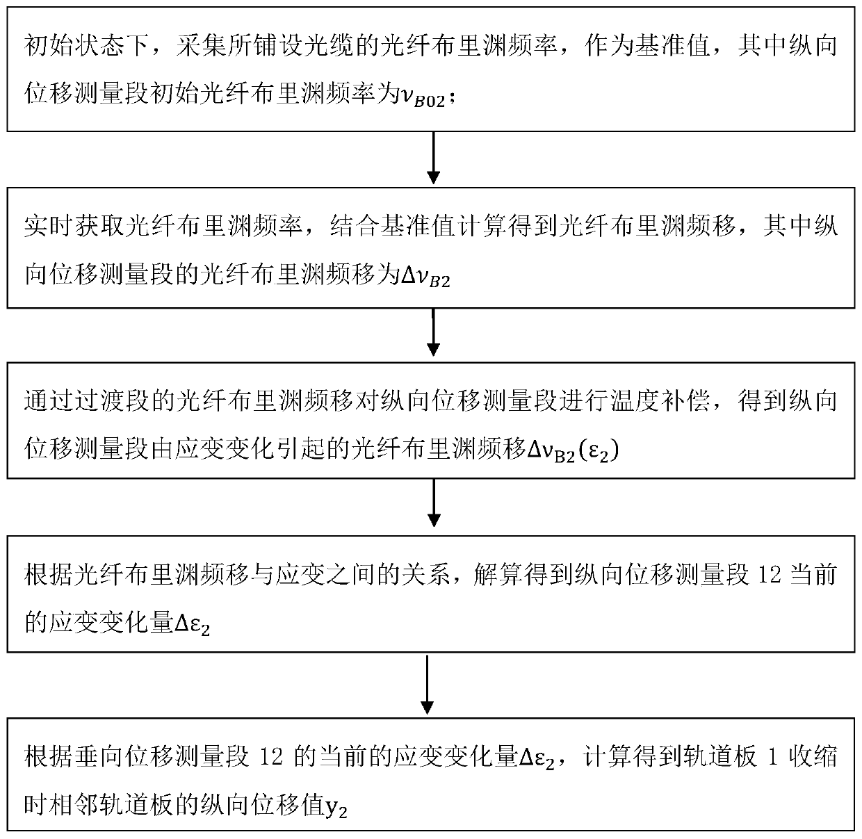
[0114] The principle and process of monitoring the longitudinal displacement of the adjacent track slabs in Embodiment 2 is roughly similar to the principle and process of monitoring the vertical displacement of the track slabs in Embodiment 1, so Embodiment 2 will be described in detail below.

[0115] When the track plate 1 is in a low temperature (for example, the weather temperature is lower than 0°), that is, the current temperature of the track plate 1 is lower than the preset second temperature threshold (for example, the second temperature threshold is 0°, the second temperature The temperature range of the threshold is not limited here) and the state duration of the current temperature is greater than the preset second time (for example, the second time is 3 to 5 hours, and the value of the second time is not specifically limited). Longitudinal displacement occurs between adjacent track plates 1, see ...


PUM


Abstract

The invention discloses a track board deformation monitoring device. The monitoring device comprises an optical cable, a fastening device and a detection host. The optical cable comprises a vertical displacement measuring section, a transition section and a longitudinal displacement measuring section which correspond to a vertical displacement measuring area, a transition area and a longitudinal displacement measuring area respectively. The vertical displacement measuring section and the longitudinal displacement measuring section are of pre-tensioned state, and the transition section is of afree state. The detection host obtains fiber signals of the vertical displacement measuring section and the longitudinal displacement measuring section, carries out temperature compensation by combining fiber signals of the transition section, and resolves to obtain vertical displacement of a track board relatively to a base plate or a supporting layer and longitudinal displacement between adjacent track boards. The invention also discloses a monitoring method and an online monitoring system, the system monitors state information of the track board in real time, and performs alarm and positioning under the condition that a preset alarm threshold is exceeded.

Description

technical field [0001] The invention belongs to the field of railway transportation safety monitoring, and in particular relates to a track slab deformation monitoring device and method and an on-line monitoring system. Background technique [0002] Ballastless track has simple structure, high strength, good stability, convenient construction and less maintenance work, and is widely used in high-speed railways. [0003] Among them, the CRTS II slab ballastless track is affected by factors such as the state of the wide and narrow joints between the slabs at the end of the track slab, the state of the mortar layer, the construction locking temperature, and the change of the ambient temperature. Seam cracking will cause diseases such as separation seams. If such problems cannot be found in time, it will bring security risks to the normal operation of the line. [0004] In the prior art, mechanical and electrical strain, displacement, inclination and other sensors are used to m...

Claims


Application Information

Patent Timeline
Patent Type & Authority Applications(China)
IPC IPC(8): G01B11/16
CPCG01B11/16
Inventor 韩自力柴雪松冯毅杰王智超暴学志凌烈鹏冯仲伟刘艳芬江成时佳斌姜子清刘浩张文达
Owner CR TECHCAL DEV CORP
Why Eureka
Try Eureka