Thermoelectric generating unit, molten salt reactor and operation method and application of molten salt reactor

A technology of temperature difference power generation and operation method, which is applied in the direction of nuclear power generation, generators using thermoelectric elements, and reduction of greenhouse gases, etc. It can solve problems such as unsatisfactory heat transfer capacity and achieve the effect of improving heat transfer capacity

Pending Publication Date: 2020-02-11
SHANGHAI INST OF APPLIED PHYSICS - CHINESE ACAD OF SCI
View PDF1 Cites 4 Cited by
  • Summary
  • Abstract
  • Description
  • Claims
  • Application Information

AI Technical Summary

Problems solved by technology

[0005] The technical problem to be solved by the present invention is to provide a new type of thermoelectric power generation unit, molten salt reactor and its Run method and application

Method used


Image

  • Thermoelectric generating unit, molten salt reactor and operation method and application of molten salt reactor
  • Thermoelectric generating unit, molten salt reactor and operation method and application of molten salt reactor
  • Thermoelectric generating unit, molten salt reactor and operation method and application of molten salt reactor

Examples


Embodiment 1

[0071] (1) molten salt reactor

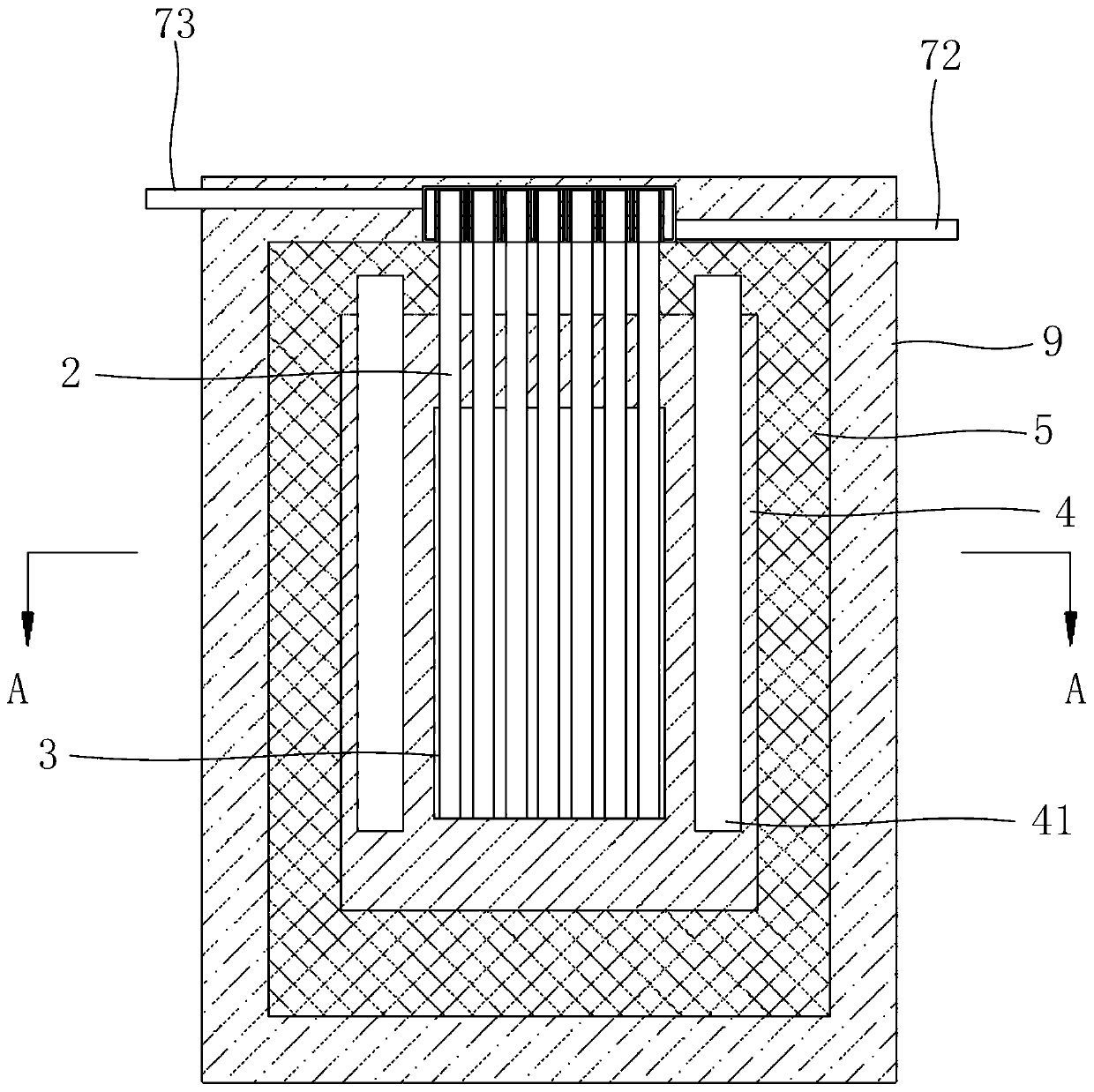
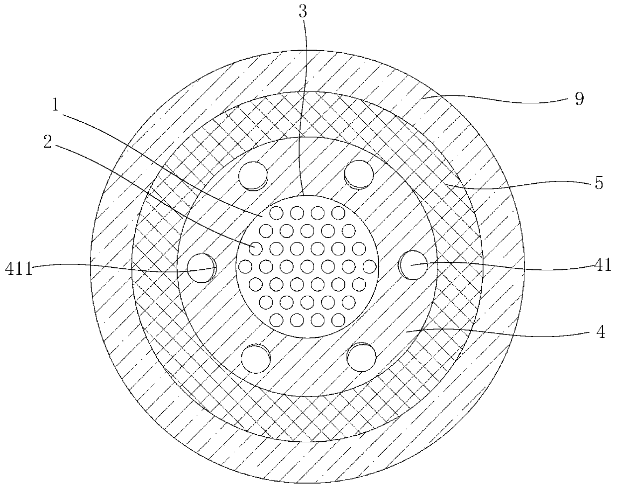
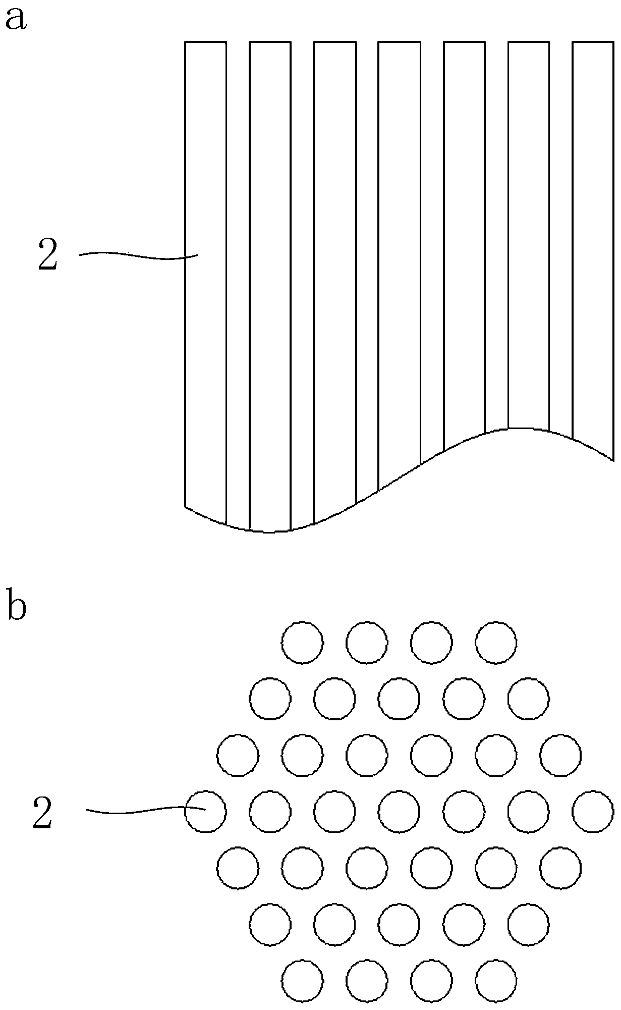
[0072] Such as Figure 1-9 As shown, the molten salt reactor includes fuel salt 1, heat pipe 2, core vessel 3, reflective layer 4 and shielding layer 5; reflective layer 4 and shielding layer 5 are arranged outside the core vessel 3 in sequence; fuel salt 1 is filled in the stack core container 3; one end of the heat pipe 2 is inserted into the fuel salt 1, and the other end of the heat pipe 2 protrudes from the shielding layer 5 of the molten salt pile as the heat pipe condensing end; each heat pipe condensing end is sleeved with a suitable Hot end sleeve 61, the outer wall of hot end sleeve 61 is a plane, the bottom of each hot end sleeve is connected with the bottom of its adjacent hot end sleeve to form a hot end sleeve 6; A suitable cold end sleeve 71 with an internal cavity is sleeved, and the bottom of each cold end sleeve communicates with the bottom of the adjacent cold end sleeve to form a cold end sleeve 7 with an internal cavity. ...

Embodiment 2

[0084] (1) molten salt reactor

[0085] The power of the molten salt reactor is 10kw, the inner diameter of the core vessel is 30cm, the distance between heat pipes is adjusted to 60mm, and the number of heat pipes is 19, and the rest are the same as the molten salt reactor in embodiment 1.

[0086] (2) Operation method

[0087] It is carried out in the above molten salt reactor, wherein the cooling water flow rate is 0.2kg / s, the inlet water temperature of the cooling water inlet is 300K, and the outlet water temperature of the cooling water outlet is 330.2K; the core temperature is 873K, and the temperature of the hot end of the thermoelectric power generation sheet is 833.2K, the temperature of the cold end of the thermoelectric power generation sheet is 517.3K, the temperature difference between the hot end and the cold end of the thermoelectric power generation sheet is 325.9K, and the rest are the same as the operation method of embodiment 1.

[0088] Technical effect: ...


PUM

PropertyMeasurementUnit
Heat transfer coefficientaaaaaaaaaa

Abstract

The invention discloses a thermoelectric generating unit, a molten salt reactor and an operation method and application of the molten salt reactor. The thermoelectric generating unit is used for condensing ends of heat pipes, and comprises hot end sleeves and cold end sleeves; the hot end sleeves are used for sleeving the condensing ends of the heat pipes, the outer side walls of the hot end sleeves are flat, and the bottom of each hot end sleeve is connected with the bottom of the adjacent hot end sleeve to form a hot end sleeve body; the cold end sleeves provided with inner cavities and matched with the hot end sleeves sleeve each hot end sleeve, the bottom of each cold end sleeve communicates with the bottom of the adjacent cold end sleeve to form a cold end sleeve body with an inner cavity, and cooling medium inlets and cooling medium outlets are formed in the cold end sleeve bodies; thermoelectric generating plates are posted between the outer side walls of the hot end sleeve bodies and the inner side walls of the cold end sleeve bodies; and the outer side walls of the hot end sleeve bodies and the inner side walls of the cold end sleeve bodies are fitted at positions where the thermoelectric generating plates are not posted The thermoelectric generating unit can improve the heat transfer capacity.

Description

technical field [0001] The invention relates to a thermoelectric power generation unit, a molten salt reactor and its operation method and application. Background technique [0002] With the development of science and technology, people are accelerating the pace of exploration of special environments such as outer space and deep sea. Traditional energy systems are not adaptable to harsh working environments such as high and low temperature, vacuum, radiation, shock and vibration due to their large size, poor battery life, etc. Strong and other reasons, it is difficult to meet the long-term work needs of large-scale special equipment. The technical development of nuclear energy power sources that are not affected by the environment, have a long life, and are safe and reliable have been paid more and more attention. [0003] Reactors suitable for special environments currently considered in the world include gas-cooled reactors and liquid-cooled reactors. Gas-cooled reactors ...

Claims


Application Information

Patent Timeline
IPC IPC(8): G21D7/04
CPCG21D7/04Y02E30/00
Inventor 陈兴伟戴叶崔德阳于世和邹杨
Owner SHANGHAI INST OF APPLIED PHYSICS - CHINESE ACAD OF SCI
Why Eureka
Try Eureka