Manual and electric switching type double-terminal change-over switch

A transfer switch and electric switching technology, applied in the direction of electric switches, circuits, electrical components, etc., can solve the problems that manual state and electric state switching cannot be realized, manual state and electric state switching is inconvenient, and dual power supply equipment control is inconvenient. , to achieve the effect of compact structure, simple structure and simplified operation process

Pending Publication Date: 2020-02-11
DONGGUAN JIYE ELECTRICAL EQUIP CO LTD
View PDF0 Cites 1 Cited by
  • Summary
  • Abstract
  • Description
  • Claims
  • Application Information

AI Technical Summary

Problems solved by technology

At present, most of the double-terminal transfer switches have complex structures, large volume, inconvenient operation, cannot realize the switching between manual state and electric state, and are inconvenient to control dual power supply equipment; although there are also manual and electric in the prior art. The double-terminal transfer switch for switching, but the manual structure and electric structure of the double-terminal transfer switch that can be switched manually and electrically in the prior art are split structures. When the manual structure is not used, the manual structure needs to be kept. In the manual state and the electric state, it is necessary to add additional buttons and components to realize the manual and electric switching. The switching between the manual state and the electric state is inconvenient and the operation is cumbersome.

Method used


Image

  • Manual and electric switching type double-terminal change-over switch
  • Manual and electric switching type double-terminal change-over switch
  • Manual and electric switching type double-terminal change-over switch

Examples


Embodiment Construction

[0024] In order to facilitate the understanding of those skilled in the art, the present invention will be further described below in conjunction with the embodiments and accompanying drawings, and the contents mentioned in the embodiments are not intended to limit the present invention.

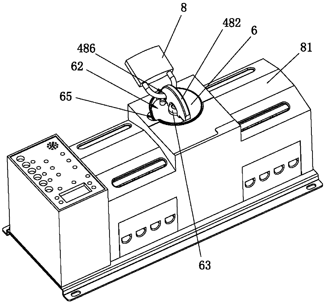
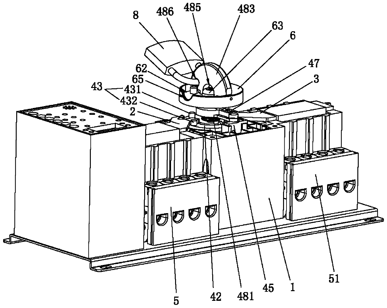
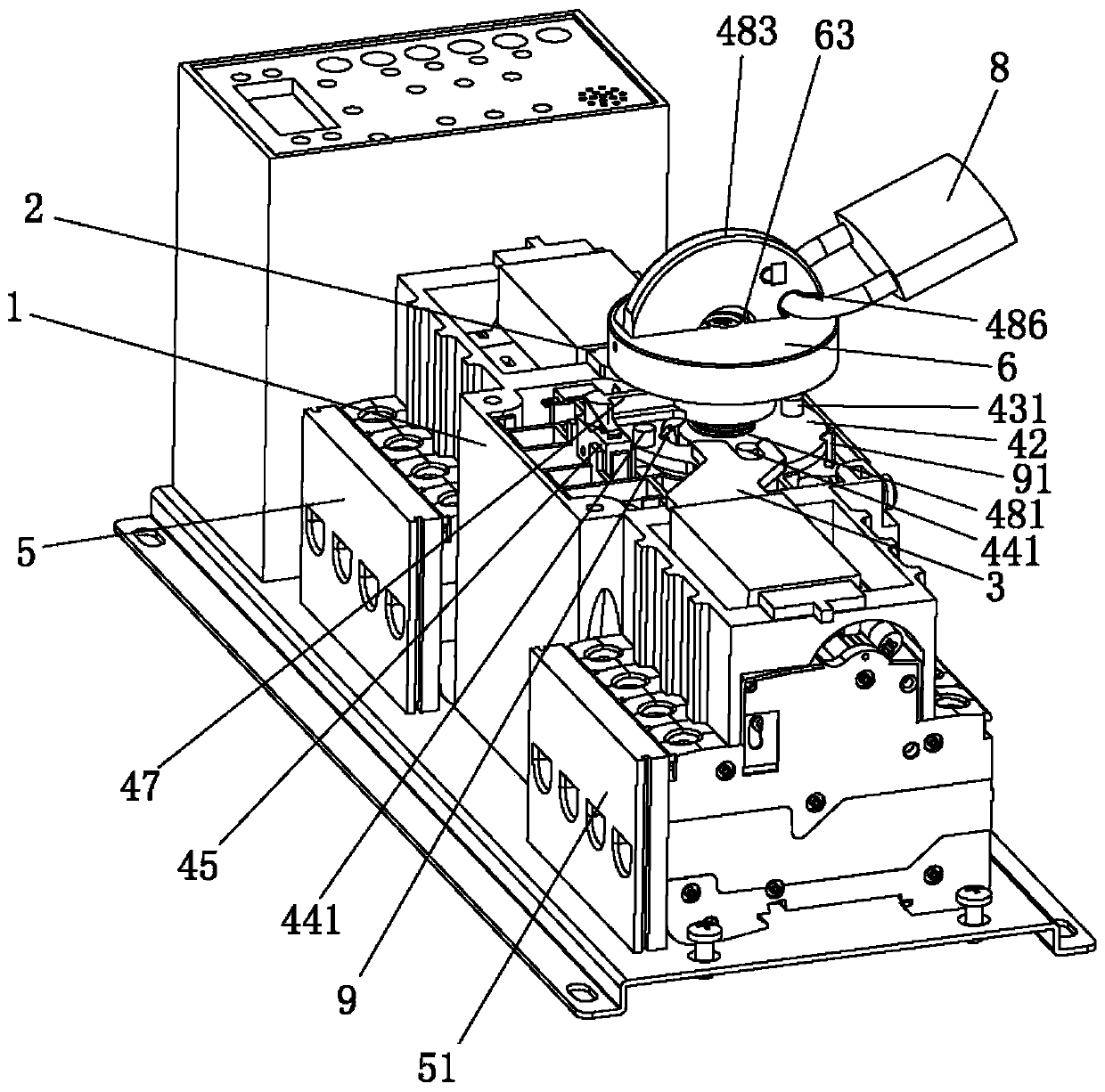
[0025] Such as Figure 1 to Figure 6 As shown, the present invention provides a manual and electric switching double-terminal transfer switch, which includes a base 1, a left paddle 2 slidably arranged on the base 1, a right paddle 3 slidably arranged on the base 1, and a drive for driving the left The driving mechanism for the movement of the paddle 2 and the right paddle 3, the driving mechanism includes a rotary driver 41 installed on the base 1, a cam plate 42 mounted on the base 1, mounted on the cam plate 42 and used to drive the left paddle 2. The moving left driving assembly 43, the right driving assembly installed on the cam plate 42 and used to drive the right paddle 3 to move, the...


PUM


Abstract

The invention relates to the control switch technology field and especially relates to a manual and electric switching type double-terminal change-over switch. The switch comprises a pedestal, a leftplectrum, a right plectrum and a driving mechanism, wherein the left plectrum and the right plectrum are slidably arranged on the pedestal, and the driving mechanism is used for driving the left plectrum and the right plectrum to move. The driving mechanism comprises a rotating driver, a cam disc rotatably arranged on the pedestal, a left driving component used for driving the left plectrum to move, a right driving component used for driving the right plectrum to move, a control unit electrically connected with the rotating driver, a starting piece used for starting and stopping the control unit, and a control component used for driving the starting piece to ascend and descend. The control unit is used for making the rotating driver be started and stopped, and an output shaft of the rotating driver is used for driving the control component and the cam disc to rotate synchronously. Manual control and electric control are integrated, manual and electric switching is convenient, an operation process is simplified, operation efficiency is improved, a manual state and an electric state are interlocked, and operation safety performance is improved.

Description

technical field [0001] The invention relates to the technical field of control switches, in particular to a manual and electric switching double-terminal changeover switch. Background technique [0002] The double-terminal transfer switch is a widely used terminal electrical appliance. It mainly controls the power supply status of the common power supply and the standby power supply in the dual-power supply equipment by driving the electric operating mechanism manually or automatically to turn on or off the common and standby power supplies, thereby Ensure the safety of the power system and the continuity of production. At present, most of the double-terminal transfer switches have complex structures, large volume, inconvenient operation, cannot realize the switching between manual state and electric state, and are inconvenient to control dual power supply equipment; although there are also manual and electric in the prior art. The double-terminal transfer switch for switch...

Claims


Application Information

Patent Timeline
Patent Type & Authority Applications(China)
IPC IPC(8): H01H1/56H01H19/20H01H19/54
CPCH01H1/56H01H19/20H01H19/54
Inventor 匡红勇聂东东苏洪新
Owner DONGGUAN JIYE ELECTRICAL EQUIP CO LTD
Why Eureka
Try Eureka