Moisture-proof electrical cabinet

A technology for electrical cabinets and cabinets, which is applied in the field of electrical cabinets, and can solve problems such as moisture, entry into the interior of the power box, and damage to power components, and achieve the effect of avoiding damage

Inactive Publication Date: 2020-02-11
EASTERN LIAONING UNIV
View PDF5 Cites 7 Cited by
  • Summary
  • Abstract
  • Description
  • Claims
  • Application Information

AI Technical Summary

Problems solved by technology

Electrical cabinets are widely used in chemical industry, environmental protection industry, power system, metallurgical system, industry, nuclear power industry, fire safety monitoring, transportation industry, etc. When the internal components of the electrical cabinet work, a lot of heat will be generated. Traditional The method is to open a plurality of cooling holes on the side wall of the electrical cabinet to dissipate heat from the power components and avoid damage to the power components. In rainy days, the surrounding air is relatively humid, and the humid air enters the inside of the power box through the cooling holes. In turn, it is easy to cause damage to power components. For this reason, we have proposed a moisture-proof electrical cabinet to solve the above problems

Method used


Image

  • Moisture-proof electrical cabinet
  • Moisture-proof electrical cabinet
  • Moisture-proof electrical cabinet

Examples


Embodiment Construction

[0018] The following will clearly and completely describe the technical solutions in the embodiments of the present invention with reference to the accompanying drawings in the embodiments of the present invention. Obviously, the described embodiments are only some, not all, embodiments of the present invention.

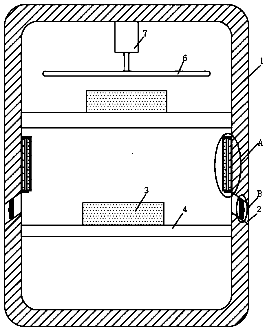
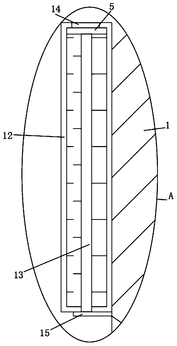
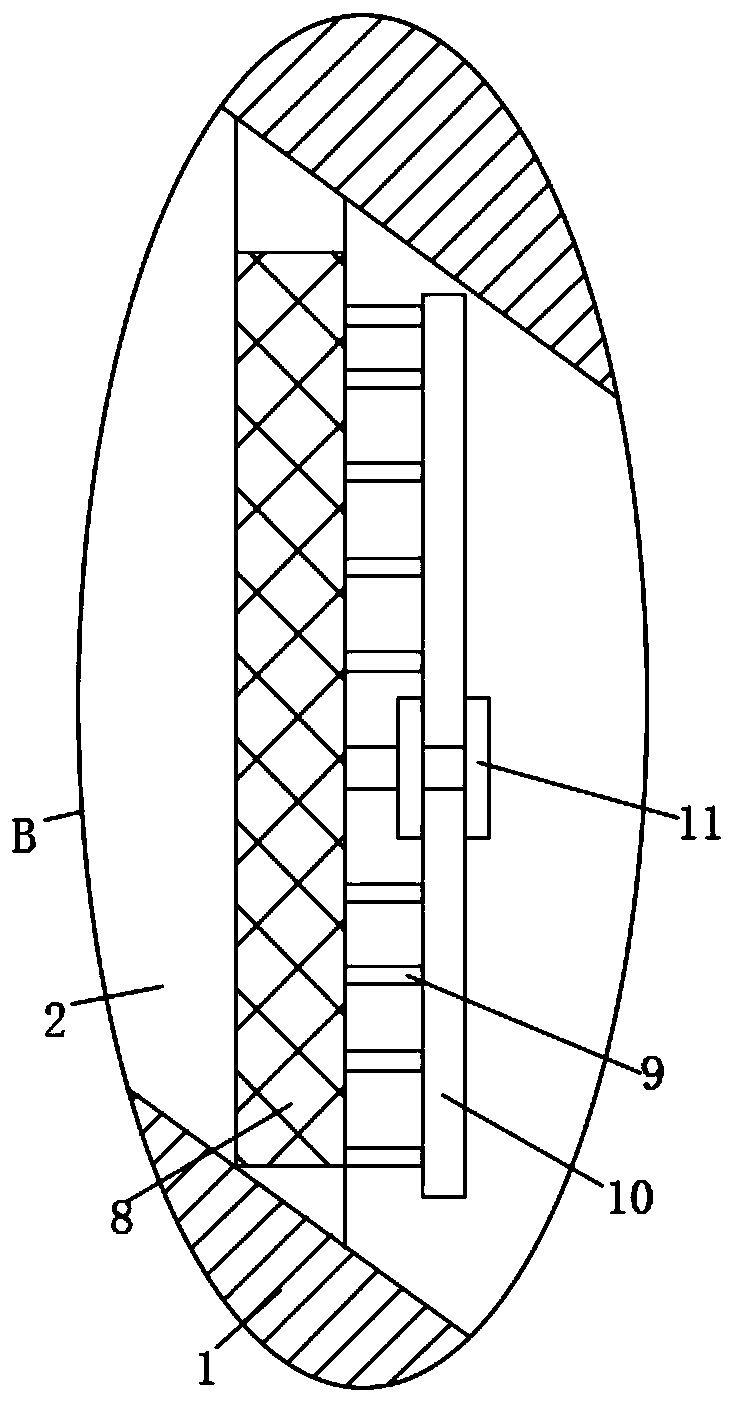
[0019] refer to Figure 1-3 , a moisture-proof electrical cabinet, including a cabinet body 1, a plurality of placement mechanisms are installed on the inner wall of the cabinet body 1, the placement mechanism includes a mounting plate 4 arranged on the inner wall of the cabinet body 1, and power components are placed on the mounting plate 4 3. A cooling mechanism is installed on the inner top of the cabinet body 1;

[0020] The heat dissipation mechanism includes a driving motor 7 arranged on the top of the cabinet body 1, the end of the output shaft of the driving motor 7 is fixedly connected with a cooling fan 6, and the inner wall of the cabinet body 1 is symmetr...


PUM


Abstract

The invention discloses a moisture-proof electrical cabinet, and relates to the field of electrical cabinets. The moisture-proof electrical cabinet includes a cabinet body. A plurality of placement mechanisms are installed on the inner side wall of the cabinet body. A heat dissipation mechanism is installed on the inner top of the cabinet body. Sealing mechanisms are symmetrically arranged on theinner side wall of the cabinet body. Heat dissipation holes are symmetrically disposed on the side wall of the cabinet body. The effective heat dissipation of power components is achieved by the cooperation of the cabinet body, a cooling fan, a drive motor, the heat dissipation holes, a dustproof plate, and a brush. A rotating shaft and rotating fan blades are rotatably connected to the side wallof the dustproof plate. During the heat dissipation process, a heat flow is discharged through the heat dissipation holes and rotates a rotating fan, thereby cleaning the dust on the side wall of a dust screen. Through the cooperation of a sealing box, a sealing rod, a communication hole, and a piston, the sealing effect of the heat dissipation holes can be achieved in rainy weather so as to prevent external humid air from entering the box, thereby protecting power components against damage.

Description

technical field [0001] The invention relates to the field of electric cabinets, in particular to a moisture-proof electric cabinet. Background technique [0002] The electrical cabinet is a cabinet made of steel to protect the normal operation of components. The materials for making electrical cabinets are generally divided into two types: hot-rolled steel plates and cold-rolled steel plates. Compared with hot-rolled steel plates, cold-rolled steel plates are softer and more suitable for the production of electrical cabinets. Electrical cabinets are widely used in chemical industry, environmental protection industry, power system, metallurgical system, industry, nuclear power industry, fire safety monitoring, transportation industry, etc. When the internal components of the electrical cabinet work, a lot of heat will be generated. Traditional The method is to open multiple cooling holes on the side wall of the electrical cabinet to dissipate heat from the power components t...

Claims


Application Information

Patent Timeline
IPC IPC(8): H02B1/30H02B1/56H02B1/28
CPCH02B1/28H02B1/30H02B1/565
Inventor 周家红
Owner EASTERN LIAONING UNIV
Why Eureka
Try Eureka