
A power generating unit

A technology for generating units and power, applied to pump components, motor vehicles, machines/engines, etc., to achieve the effects of fewer assembly steps, simplified connections, and simplified assembly

Active Publication Date: 2020-02-11
VOLVO LASTVAGNAR AB +1
View PDF7 Cites 0 Cited by
  • Summary
  • Abstract
  • Description
  • Claims
  • Application Information

AI Technical Summary

Problems solved by technology

[0004] Although the power generation unit described in WO 2007 / 058594 is capable of adequately supplying hydraulic pressure and hydraulic flow to driven accessories, further improvements are still needed in terms of eg the flexibility of connecting the power generation unit to an internal combustion engine or other stationary units

Method used


Image

  • A power generating unit
  • A power generating unit
  • A power generating unit

Examples


Embodiment Construction

[0036] The present invention will now be described more fully hereinafter with reference to the accompanying drawings, in which exemplary embodiments of the invention are shown. However, this invention may be embodied in many different forms and should not be construed as limited to the embodiments set forth herein; rather, these embodiments are provided for thoroughness and completeness. Throughout the specification, the same reference numerals denote the same elements.

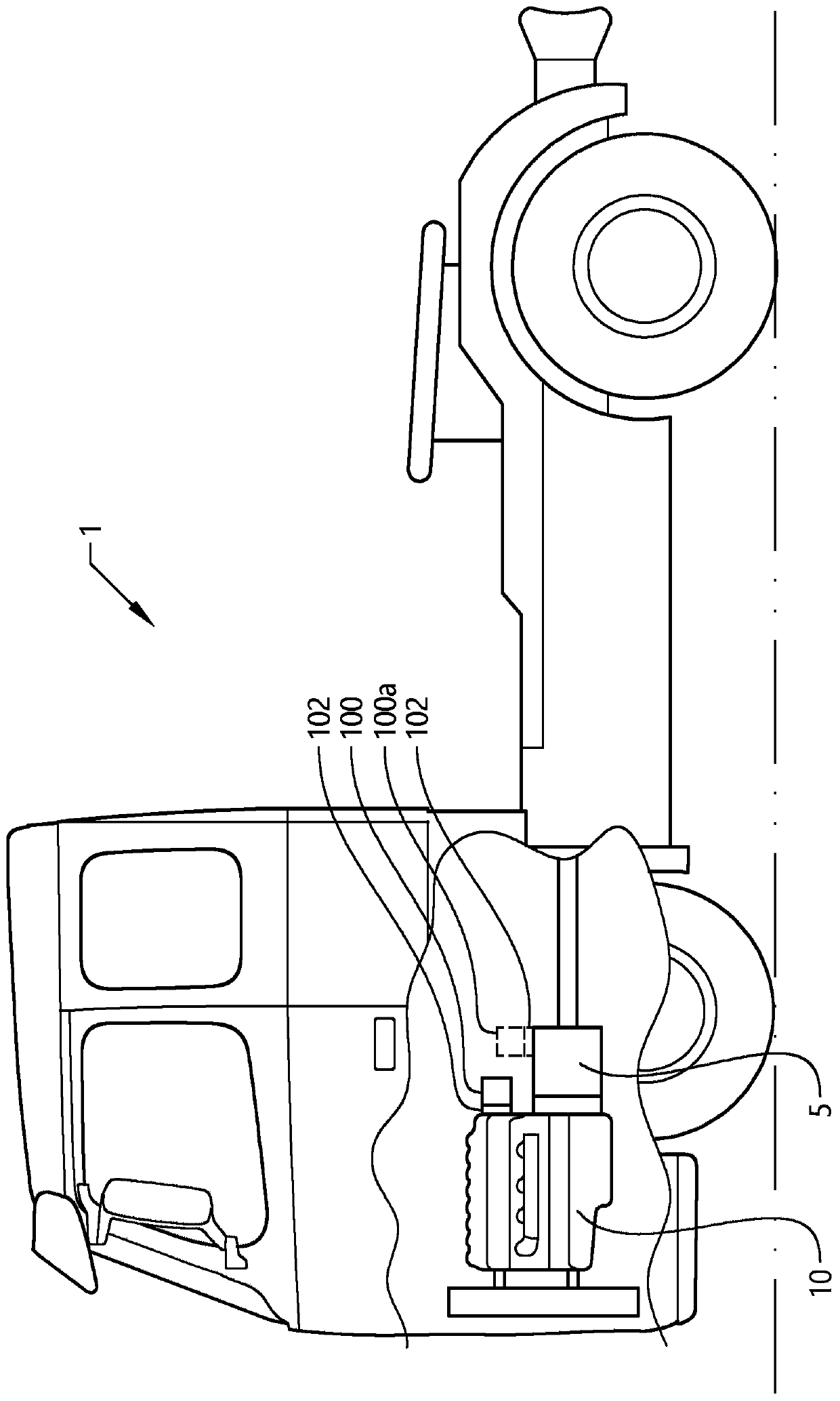
[0037] special reference figure 1 , depicts a vehicle 1 in the form of a truck to which the power generating unit 100 to be described below is particularly suitable. However, the power generation unit 100 may also be provided and used in other applications, such as agricultural machinery, fans, cranes, engines used in process industries, and the like. However, for simplicity, the power generation unit 100 will be described below only for a truck. Such as figure 1 As shown in , the vehicle comprises a pri...


PUM


Abstract

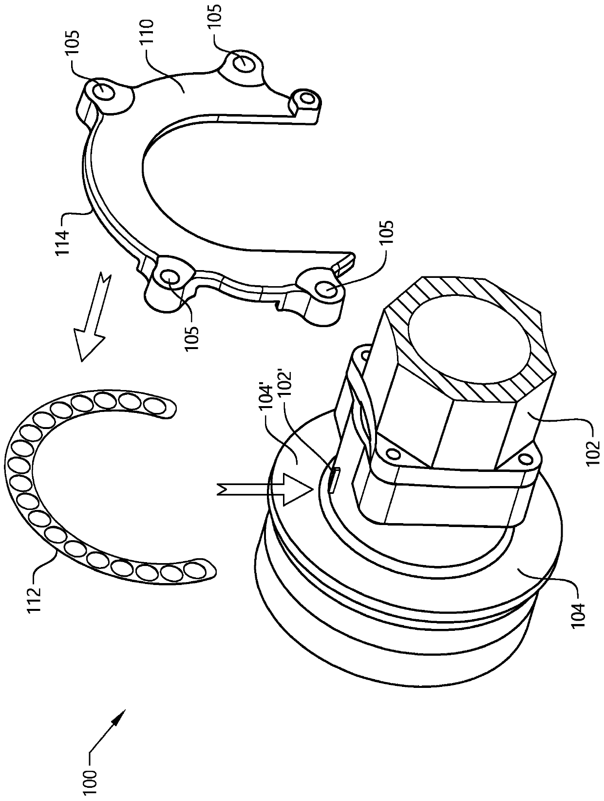
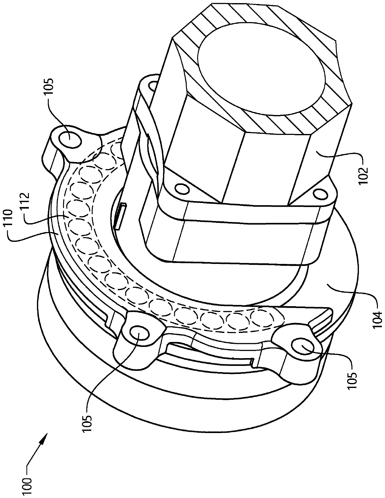
The present invention relates to a power generating unit (100, 200, 400) comprising a hydraulic unit (102, 202, 402); an interface unit (104, 204, 404) connected to the hydraulic unit (102, 202, 402),said interface unit (104, 204, 404) being connectable to a stationary unit; a power flow shaft (302) connected between the hydraulic unit (102, 202, 402) and the interface unit (104, 204, 404) for supply of a torque load there between; and at least one connecting element (110, 210, 410) arranged between the hydraulic unit (102, 202, 402) and the interface unit (104, 204, 404), said at least one connecting element (110, 210, 410) being controllable between a first state in which a relative rotation between the hydraulic unit (102, 202, 402) and the interface unit (104, 204, 404) is allowed, and a second state in which a relative rotation between the hydraulic unit (102, 202, 402) and the interface unit (104, 204, 404) is prevented.

Description

technical field [0001] The invention relates to a power generating unit. The invention is applicable to vehicles, particularly light, medium and heavy duty vehicles commonly referred to as trucks. Background technique [0002] Power generation units are commonly used in various applications, such as those within the vehicular field. The power generation unit is arranged to handle a load in rotation and power can be transferred from the unit mechanically via a power flow shaft, or hydraulically, for example by fitting a hydraulic unit to the power generation unit. The hydraulic unit may for example be a hydraulic pump, whereby the power generation unit is connected to a source of rotational energy of the vehicle capable of propelling the pump. [0003] A power generation unit comprising such a hydraulic pump is described in WO 2007 / 058594. As described herein, the power generation unit can be mounted to the housing of the internal combustion engine. The power generation u...

Claims


Application Information

Patent Timeline
IPC IPC(8): F04B41/06B60K25/06F04D13/02F04D29/60
CPCB60K25/06F04B9/02F04B17/05F04B17/06F03C1/00F04D13/021B60Y2200/14B60Y2200/142F04B53/22F04D29/605
Inventor 本尼·利耶布拉德斯特凡·约翰逊拉尔斯·R·尼尔森
Owner VOLVO LASTVAGNAR AB
Learn More