

Sole pressing assembly line for shoemaking and sole pressing method
An assembly line and shoe technology, applied to shoe soles, shoemaking machinery, footwear, etc., can solve problems such as inability to adjust or limit side pressure rubber blocks, uneven front and rear pressure, and low production efficiency, so as to ensure smooth operation , to achieve the effect of quick disassembly and quick assembly, uniform extrusion force
- Summary
- Abstract
- Description
- Claims
- Application Information
AI Technical Summary
Problems solved by technology
Method used
Image

Examples
Embodiment Construction
[0037] In order to make the above-mentioned features and advantages of the present invention more comprehensible, the following specific embodiments will be described in detail with reference to the accompanying drawings.
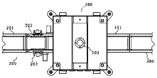
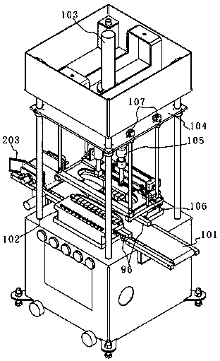
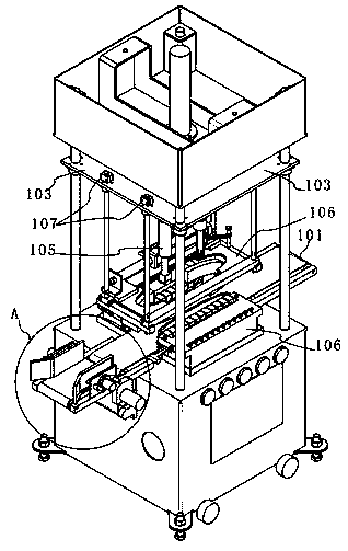
[0038] Such as Figure 1-13 As shown, this embodiment provides a bottom pressing line for shoemaking, including an electric control system, a bottom pressing unit 100, a feeding unit 200 adjacent to the input end of the bottom pressing unit 100 for inputting processed products, and a bottom pressing unit adjacent to the bottom pressing unit 100. The output end of the unit 100 is the unloading unit 300 for outputting the processed products after the bottom pressing operation is completed. Both the feeding unit 200 and the bottom pressing unit 100 are electrically connected to the electronic control system. The unloading unit 300 is based on the actual It is required to choose whether to be electrically connected to the electric control system. The electric c...
PUM
 Abstract
Description
Claims
Application Information