Integrated veneer lathe with and without spindle
A rotary cutting machine and integrated technology, applied in the manufacture of thin wood chips, wood processing equipment, manufacturing tools, etc., can solve the problems of difficult drive speed, machine and log damage, etc., and achieve good uniformity and smoothness, and uniform extrusion force, no back crack effect
- Summary
- Abstract
- Description
- Claims
- Application Information
AI Technical Summary
Problems solved by technology
Method used
Image
Examples
Embodiment 1
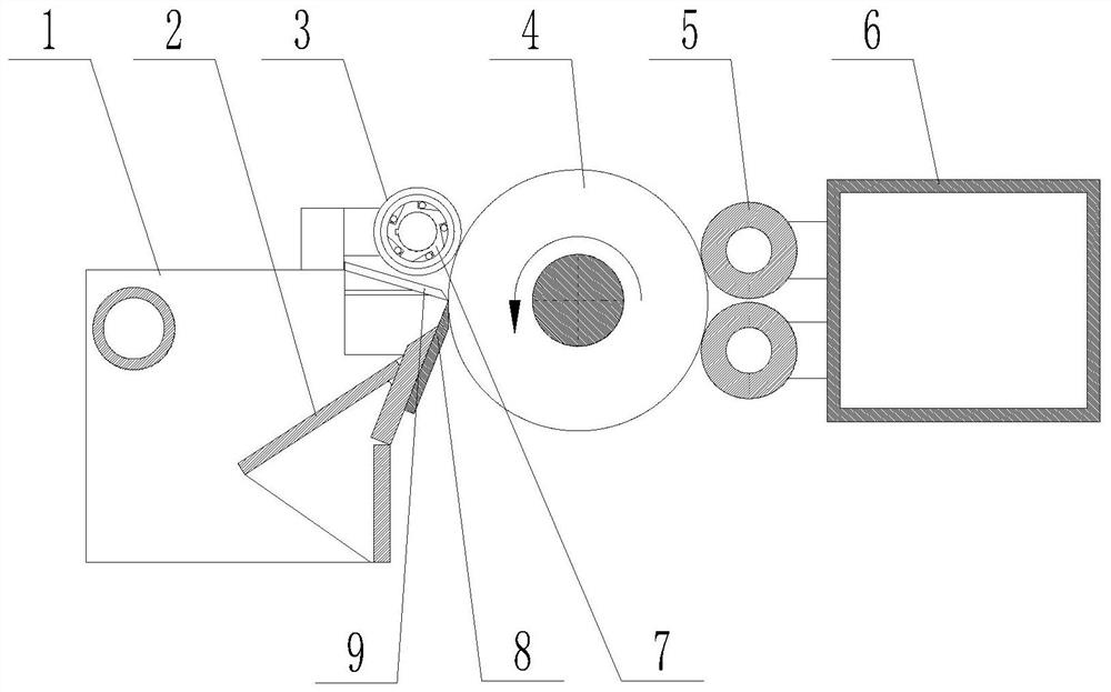
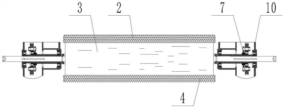
[0020] Such as figure 1 , figure 2 As shown, the card-free integrated rotary cutting machine described in this embodiment includes a frame, and the frame is provided with a knife holder 1, a knife holder 2, a pressure gauge roller 3, a double roller 5, a double roller seat 6, a rotary Cutter 8 and clamping shaft mechanism 10, knife rest 2 and pressure scale roller 3 are arranged on the knife seat 1, rotary cutter 8 is located on the knife rest 2, double roller 5 is installed on the double roller seat 6, clamping shaft mechanism 10 A clutch is installed on it.
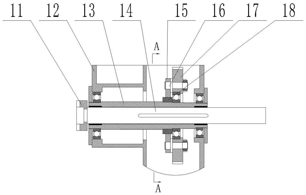
[0021] Such as image 3 , Figure 4 As shown, the clamping shaft mechanism 10 includes a claw 11, a clamping box 12, a sliding sleeve 13, a clamping shaft 14 and a gear 17. The clamping claw 11 is fixedly connected to the clamping shaft 14, and the clamping shaft 14 is connected in the sliding sleeve 13 through a keyway. Relative to the sliding sleeve 13, it can move axially and simultaneously rotate with the slidi...
Embodiment 2
[0026] Such as figure 1 As shown, the card-free integrated rotary cutting machine described in this embodiment includes a frame, and the frame is provided with a knife holder 1, a knife holder 2, a pressure gauge roller 3, a double roller 5, a double roller seat 6, a rotary Cutter 8 and clamping shaft mechanism 10, knife rest 2 and pressure scale roller 3 are arranged on knife rest 1, rotary cutter 8 is located on knife rest 2, double roller 5 is installed on double roller seat 6, pressure scale roller 3 Or the clutch 7 is installed on the double roller 5, and the clutch 7 on the pressure scale roller 3 or the double roller 5 is an overrunning clutch.
[0027] The working principle of this embodiment: when working, at first the clamping shaft 14 is retreated along the sliding sleeve 13, the center of the log 4 is placed on the clamping shaft 14, the clamping shaft 14 advances to block the center of the log 4, and then the pressure gauge roller 3 and The double roller 5 clamps...
Embodiment 3
[0029] Such as Figure 1-4 As shown, the card-free integrated rotary cutting machine described in this embodiment includes a frame, and the frame is provided with a knife holder 1, a knife holder 2, a pressure gauge roller 3, a double roller 5, a double roller seat 6, a rotary Cutter 8 and clamping shaft mechanism 10, knife rest 2 and pressure scale roller 3 are arranged on knife rest 1, rotary cutter 8 is located on knife rest 2, double roller 5 is installed on double roller seat 6, pressure scale roller 3 , double rollers 5 and the card shaft mechanism 10 are equipped with clutch 7.
[0030] The working principle of this embodiment: when working, at first the clamping shaft 14 is retreated along the sliding sleeve 13, the center of the log 4 is placed on the clamping shaft 14, the clamping shaft 14 advances to block the center of the log 4, and then the pressure gauge roller 3 and The double roller 5 clamps the log 4, then starts the driving power of the card shaft mechanis...
PUM
 Abstract
Description
Claims
Application Information
 - R&D
- Intellectual Property
- Life Sciences
- Materials
- Tech Scout
- Unparalleled Data Quality
- Higher Quality Content
- 60% Fewer Hallucinations
Browse by: Latest US Patents, China's latest patents, Technical Efficacy Thesaurus, Application Domain, Technology Topic, Popular Technical Reports.
© 2025 PatSnap. All rights reserved.Legal|Privacy policy|Modern Slavery Act Transparency Statement|Sitemap|About US| Contact US: help@patsnap.com


