Eureka AIR delivers breakthrough ideas for toughest innovation challenges, trusted by R&D personnel around the world.

Automatic ultrasonic coupling agent smearing device

An ultrasonic coupling agent and automatic technology, which is applied in the field of ultrasonic medicine, can solve the problems of insufficient automaticity, single application method, and inability to fit the skin surface well, so as to achieve the effect of good automation and high work efficiency

Active Publication Date: 2020-02-14
南京微电射频技术有限公司
View PDF13 Cites 4 Cited by
  • Summary
  • Abstract
  • Description
  • Claims
  • Application Information

AI Technical Summary

Problems solved by technology

However, manual application is time-consuming and laborious, so an automatic application device is needed to improve work efficiency
There are also some equipment, such as a couplant applicator of [CN 207591099U], which is only used to assist in smearing, and still requires manual operation, which cannot really improve efficiency; another example is the ultrasonic inspection couplant of [CN 207755296 U]. Applicator, the smearing surface of the device in contact with the epidermis is flat, the smearing method is relatively simple, it cannot fit the skin surface well, and it is not automatic enough to achieve automatic smearing

Method used


Image

  • Automatic ultrasonic coupling agent smearing device
  • Automatic ultrasonic coupling agent smearing device
  • Automatic ultrasonic coupling agent smearing device

Examples


Embodiment 2

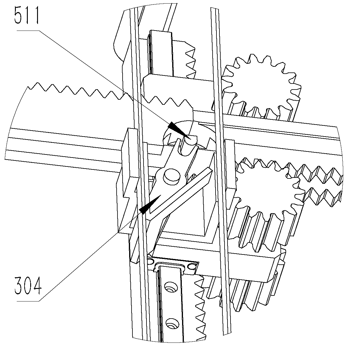
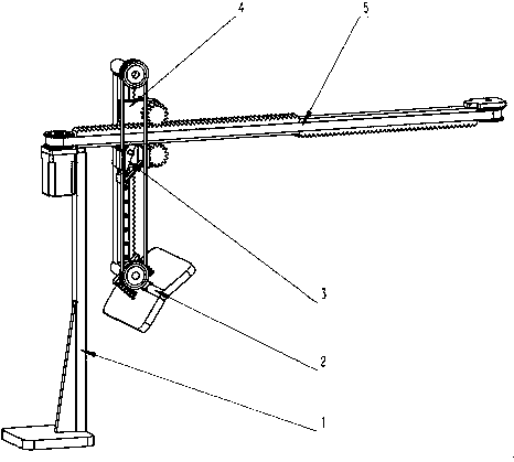
[0027] Embodiment 2: The rest of this embodiment is the same as the previous embodiment. When the lower end of the reversing lever 304 swings to the left, cooperate with the timing belt stopper 303 to fix the left side of the second synchronous belt 302; the reversing lever When the lower end of 304 swings to the right, cooperate with the synchronous belt limit block 303 to fix the second synchronous belt 302 right side.

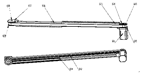
[0028] The transverse driving mechanism 5 comprises a motor 501, a first synchronous wheel 504, a second synchronous wheel 509, a second synchronous wheel shaft 508, a first synchronous belt 503, a motor fixed plate 502, a pulley fixed plate 507, a long slotted rack 505, Short slotted rack 506, reversing limit head 511, horizontal guide rail 510; long slotted rack 505 has a groove on one plane side, and one side is fixed to the side of short slotted rack 506; short slotted rack The 506 tooth surface side has a groove; the motor fixing plate 502 is fixed on o...

Embodiment 3

[0029]Embodiment 3: the remainder of this embodiment is the same as the previous embodiment, and the smearing mechanism 2 includes a smearing panel 203, a smearing bracket 204, a support shaft 201, and a panel spring 202; the lower end of the smearing bracket 204 is connected with the smearing panel 203; the smearing panel 203 can Swing around the smearing bracket 204, the upper side of the smearing panel 203 is connected to one side of the panel spring 202; one side of the panel spring 202 is connected to the smearing panel 203, and the other side is connected to the protruding ends of the smearing bracket 204; the bracket shaft 201 is connected to the smearing bracket The upper end of 204 is fixed and fixed with the fourth synchronous wheel 305; it is connected with the lower end of the vertical rack 402 and can rotate freely; the smearing panel can provide a certain number of couplant output holes as required. The bottom panel of the support 1 is fixed on other surfaces, and...


PUM


Abstract

The invention discloses an automatic ultrasonic coupling agent smearing device. The smearing device comprises a support, a transverse driving mechanism, a vertical driven mechanism, a smearing turningmechanism and a smearing mechanism. The smearing turning mechanism in the device enables the smearing mechanism to change the direction in the moving process, and the smearing mechanism is more suitable for most skin surface shapes subjected to ultrasonic examination; when the vertical driven mechanism moves, the vertical driven mechanism can cooperatively move to all positions of the upper surface of the skin; in combination with a transverse moving mechanism, the smearing surface of the smearing mechanism can be in an arc shape, and work can be completed only through one motor; and the device is high in working efficiency and good in automation degree.

Description

technical field [0001] The invention relates to the technical field of ultrasonic medicine, in particular to an automatic application device for ultrasonic coupling agent. Background technique [0002] The development of ultrasound medicine in today's medical field has made the application of ultrasound medicine more and more extensive in clinical practice. Before an ultrasound examination, a gel must be applied to the skin surface in contact with the ultrasound probe. However, manual application is time-consuming and laborious each time, so an automatic application device is needed to improve work efficiency. There are also some equipment, such as a couplant applicator of [CN 207591099U], which is only used to assist in smearing, and still requires manual operation, which cannot really improve efficiency; another example is the ultrasonic inspection couplant of [CN 207755296 U]. As for the applicator, the smearing surface of the device in contact with the epidermis is fla...

Claims


Application Information

Patent Timeline
IPC IPC(8): A61B8/00A61M35/00
CPCA61B8/4281A61M35/003
Inventor 雷磊
Owner 南京微电射频技术有限公司
Why Eureka
Eureka Blog
Learn More