
Electric anastomat and control system thereof

A control system and stapler technology, applied in the field of medical devices, can solve problems such as damage, judgment of cutting components and stapler body, and misoperation of instruments

Pending Publication Date: 2020-02-14
SHANDONG WEIRUI SURGICAL MEDICAL PROD
View PDF0 Cites 11 Cited by
  • Summary
  • Abstract
  • Description
  • Claims
  • Application Information

AI Technical Summary

Problems solved by technology

However, in the prior art, there is no judgment on whether the cutting assembly and the stapler body are installed normally. When the cutting assembly is not installed or installed incorrectly, if the firing action is performed, it will cause malfunction or damage to the instrument.

Method used


Image

  • Electric anastomat and control system thereof
  • Electric anastomat and control system thereof
  • Electric anastomat and control system thereof

Examples


Embodiment Construction

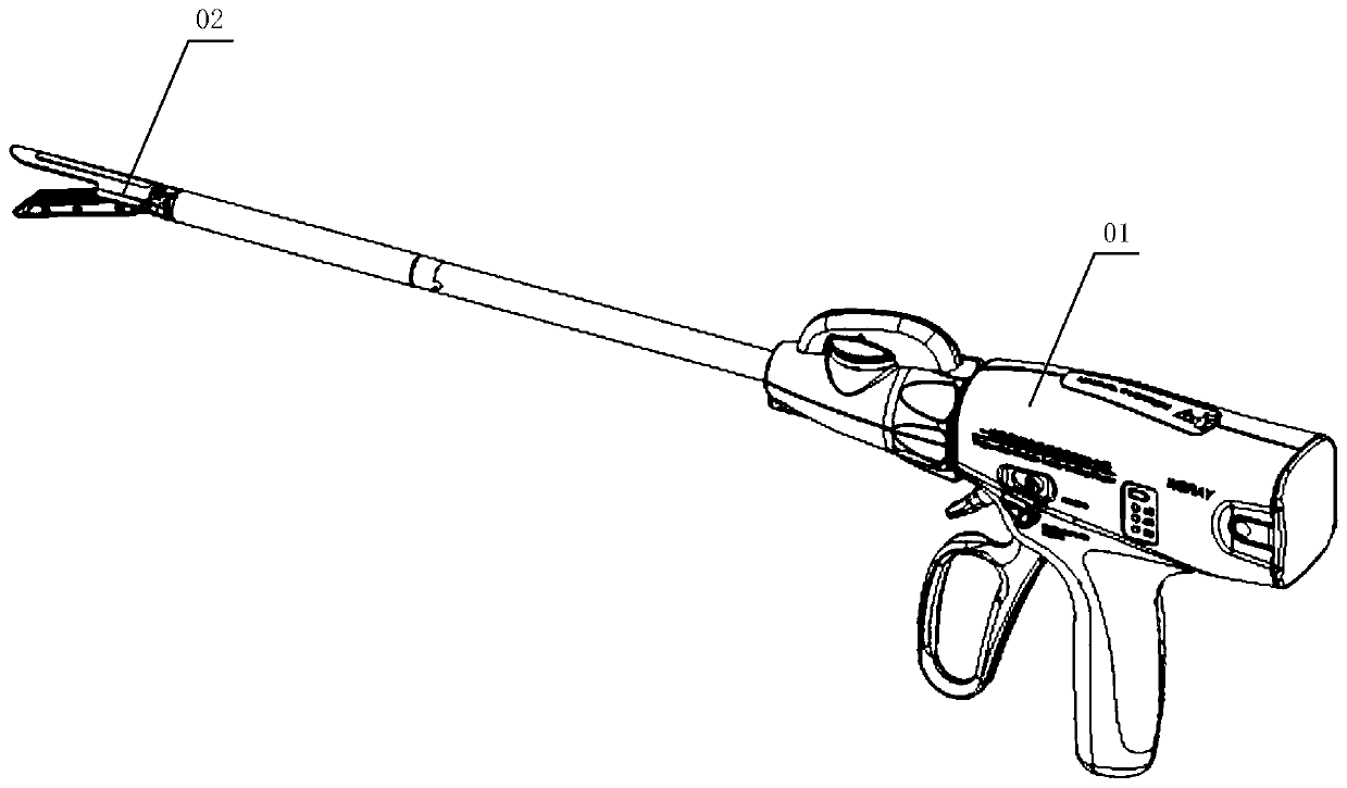
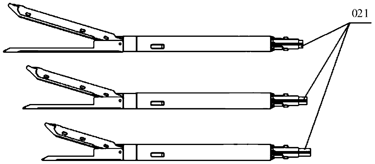
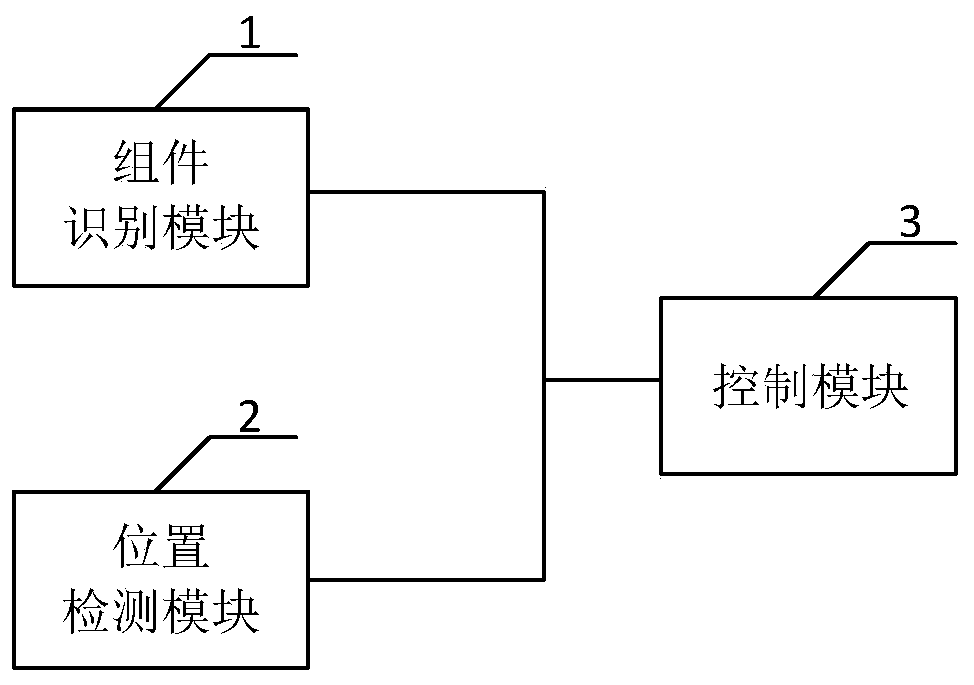
[0057] The core of this application is to provide a control system for an electric stapler, which can prevent the firing action when the cutting assembly is not installed or not installed correctly, resulting in malfunction or instrument damage; another core of this application is An electric stapler including the above control system is provided.

[0058]In order to make the purposes, technical solutions and advantages of the embodiments of the present application clearer, the technical solutions in the embodiments of the present application will be clearly and completely described below in conjunction with the drawings in the embodiments of the present application. Obviously, the described embodiments It is a part of the embodiments of this application, not all of them. Based on the embodiments in this application, all other embodiments obtained by persons of ordinary skill in the art without making creative efforts belong to the scope of protection of this application.

[...


PUM


Abstract

The invention discloses an electric anastomat and a control system thereof. The electric anastomat comprises an assembly recognition module, a position detection module and a control module, wherein the assembly recognition module is used for generating an effective signal of recognition when a cutting assembly is normally connected with an anastomat body; the position detection module is used forgenerating an effective signal of an initial point when the cutting assembly moves to the initial point; the control module is used for controlling the cutting assembly to execute cutting anastomosisoperation according to a first triggering signal output by a triggering switch after receiving the effective signal of recognition and the effective signal of the initial point. According to the electric anastomat and the control system thereof, whether the cutting assembly is normally connected with the anastomat body or not is judged through the assembly recognition module, whether the cuttingassembly reaches the initial position of a cutting stroke or not is judged through the position detection module, and the control module can respond to the first triggering signal output by the triggering switch after receiving the effective signals output by the assembly recognition module and the position detection module, so that misoperation or instrument damage caused by the triggering actionwhich is implemented under the condition that the cutting assembly is not installed or not correctly installed is prevented.

Description

technical field [0001] This application relates to the field of medical devices, in particular to an electric stapler and its control system. Background technique [0002] With the popularization of electrosurgical instruments, in order to reduce the burden on the hands of doctors and the adverse effects caused by hand shaking during firing, electric staplers have been used in open or minimally invasive general surgery, thoracic surgery, and urology. Very wide range of applications. At present, electric staplers include at least two switchable cutting components connected to the stapler body. Doctors can replace the cutting components according to surgical needs, thereby prolonging the number of times the stapler body is used in the same operation and reducing the overall cost of use. However, in the prior art, there is no judgment on whether the cutting assembly and the stapler body are installed normally. When the cutting assembly is not installed or installed incorrectly...

Claims


Application Information

Patent Timeline
Patent Type & Authority Applications(China)
IPC IPC(8): A61B17/068
CPCA61B17/068
Inventor 姚大强王翠英和题朱东东陈兆伟
Owner SHANDONG WEIRUI SURGICAL MEDICAL PROD
Learn More