Computer mainboard resistor pin bending machine
A computer motherboard and bending device technology, which is applied in the direction of assembling printed circuits with electrical components, can solve the problems of operator's sore hands, slow resistance speed, easy to stab the operator's fingers, etc.
- Summary
- Abstract
- Description
- Claims
- Application Information
AI Technical Summary
Problems solved by technology
Method used
Image

Examples
Embodiment 1
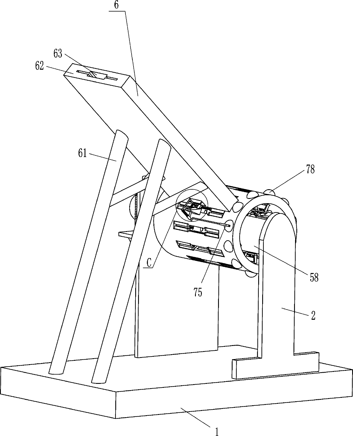
[0023] A kind of computer motherboard resistance pin bender, such as Figure 1-4 As shown, it includes a base 1 and a supporting plate 2. The base 1 is welded with supporting plates 2 on both the front and rear sides. It also includes a geared motor 3, a hollow cylinder 31, a bending device 4, a clamping device 5 and a feeding Mechanism 6, the rear support plate 2 is equipped with a geared motor 3 through bolts, the output shaft of the geared motor 3 penetrates the rear support plate 2, and a hollow cylinder 31 is installed on the output shaft in a keyed manner. The hollow cylinder 31 is provided with a bending device 4, the bending device 4 is used to bend the pins of the resistance, the bending device 4 is located between the two supporting plates 2, the hollow cylinder 31 is provided with a clamping device 5, the The clamping device 5 is used for clamping resistance components, and the base 1 is provided with a feeding mechanism 6 on the right side, and the feeding mechanism ...
Embodiment 2
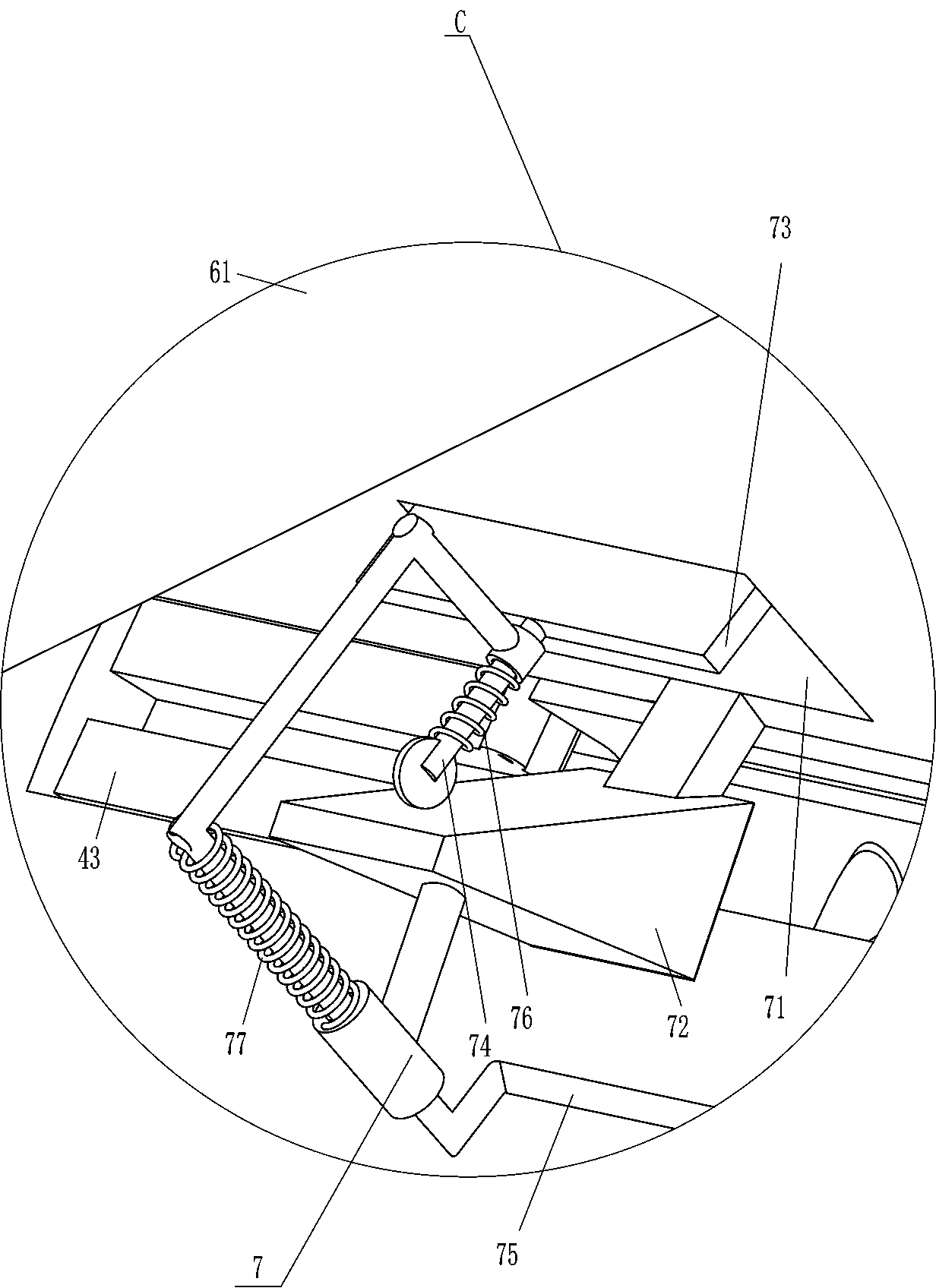
[0029] On the basis of Example 1, such as Figure 1-6 As shown, it also includes a pushing device 7, which includes an inclined block 72, a pushing plate 73, a vertical sliding rod 74, a special-shaped contact rod 75, a fifth spring 76, a sixth spring 77 and a movable protrusion 78. An opening 71 is opened on the lower right side of the inclined plate 62, and the opening 71 is communicated with the discharging slot 63. The lower right side of the inclined plate 62 is fixedly connected with an inclined block 72, and the opening 71 is provided with a resistor element for pushing A vertical sliding rod 74 is fixedly connected to the lower part of the material pushing plate 73, and the vertical sliding rod 74 is in contact with the inclined block 72. The vertical sliding rod 74 is slidably provided with a special-shaped contact rod 75 The special-shaped contact rod 75 is slidably arranged on the inclined block 72, a fifth spring 76 is connected between the vertical sliding rod 74 an...
Embodiment 3
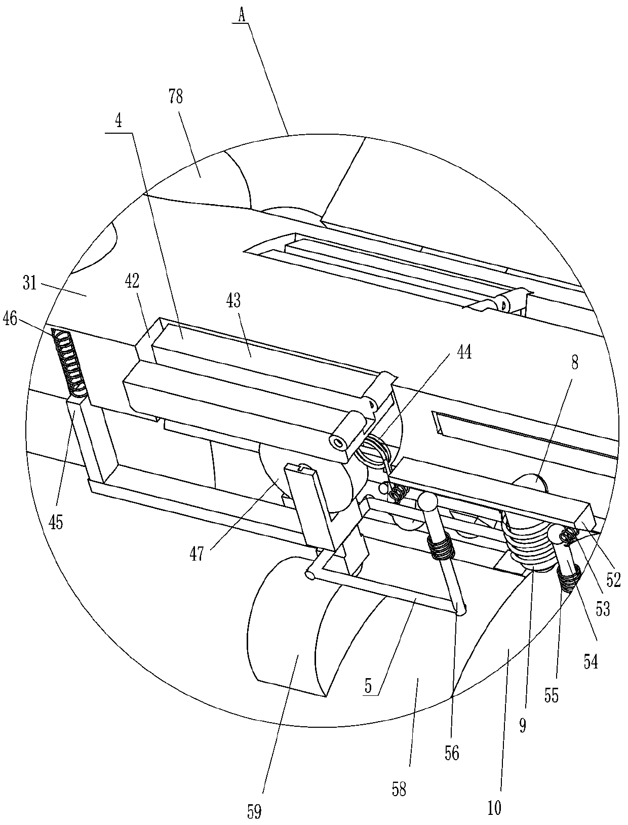
[0032] On the basis of Example 2, such as Figure 1-5 As shown, it also includes an ejector rod 8, a seventh spring 9 and an annular protrusion 10. The hollow cylinder 31 is slidably provided with an ejector rod 8, and a second rod is connected between the ejector rod 8 and the hollow cylinder 31. Seven springs 9, the ejector rod 8 is located in the special-shaped opening 42, an annular protrusion 10 is installed in the middle of the cylinder 58, and the annular protrusion 10 is in contact with the ejector rod 8.
[0033] When the ejector rod 8 is in contact with the annular protrusion 10, the ejector rod 8 can move outward, and the seventh spring 9 is compressed accordingly, and the ejector rod 8 can push out the resistance after the lead is bent, so that resistance can be avoided It is stuck in the special-shaped opening 42.
PUM
 Abstract
Description
Claims
Application Information
 - R&D
- Intellectual Property
- Life Sciences
- Materials
- Tech Scout
- Unparalleled Data Quality
- Higher Quality Content
- 60% Fewer Hallucinations
Browse by: Latest US Patents, China's latest patents, Technical Efficacy Thesaurus, Application Domain, Technology Topic, Popular Technical Reports.
© 2025 PatSnap. All rights reserved.Legal|Privacy policy|Modern Slavery Act Transparency Statement|Sitemap|About US| Contact US: help@patsnap.com