Clamping and fixing device for oil nozzle of automobile

A technology for fixing devices and fuel injection nozzles, applied in positioning devices, workpiece clamping devices, clamping, etc., can solve problems such as poor fixability of clamping fixtures, increased computing costs, and defective product rates

Inactive Publication Date: 2020-02-14
王爱民
View PDF0 Cites 0 Cited by
  • Summary
  • Abstract
  • Description
  • Claims
  • Application Information

AI Technical Summary

Problems solved by technology

When the existing automotive fuel injectors are being processed, the clamping fixture is extremely poor in fixity, which can easily cause the flange ring of the automobile to shake during processing, which affects the processing accuracy, greatly increases the rate of defective products, and increases the calculation cost , and usually the clamping fixture can only fix a single fixture and process it through processing equipment, the processing efficiency is poor, and it cannot meet the needs of industrialized mass production. Therefore, it is urgent for those skilled in the art to design a new type of clamping and fixing device

Method used


Image

  • Clamping and fixing device for oil nozzle of automobile
  • Clamping and fixing device for oil nozzle of automobile

Examples


Embodiment 1

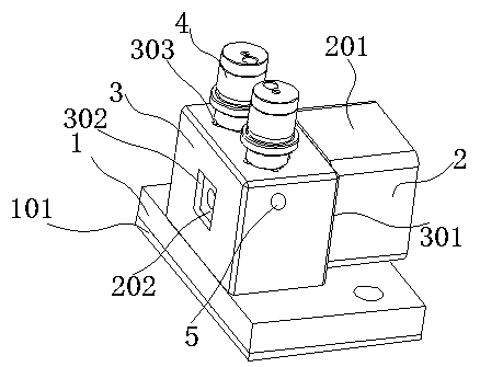
[0015] Embodiment 1: A clamping and fixing device for fuel injectors for automobiles, including a position limiting base 1, a setback fixing block 2, a positioning clamp 3 and a fuel injector workpiece 4, and the position limiting base 1 is provided with a positioning The card seat 3 is fixedly connected by welding, the nozzle workpiece 4 is sleeved in the positioning card seat 3 by the upper end and is connected with the limit base 1 in a rotating and separate manner, and the setback fixing block 2 is connected by the side end Socketed in the positioning card seat 3 and fix the fuel injection nozzle workpiece 4, the fixed block 2 and the positioning card seat 3 are fixedly connected by the fixing part 5, and the fixing part 5 is a connecting bolt, and the connecting bolt Made of alloy casting as one piece structure.

Embodiment 2

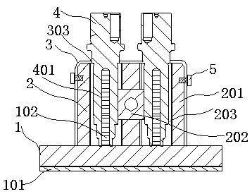
[0016] Embodiment 2: The bottom of the limiting base 1 is bonded with an anti-skid layer 101, and the anti-skid layer 101 is integrally formed by injection molding of polyurethane rubber. The limiting base 1 is equipped with a threaded protruding rod 102. The inner cavity is a threaded groove 401, and the threaded groove 401 is rotationally and fixedly connected with the threaded convex rod 102, and the rest of the technical solutions are the same as those in the first embodiment.

Embodiment 3

[0017] Embodiment 3: Make way to fix the block 2 includes a block body 201, a positioning clamp 202 and a through relief groove 203, the front end of the block body 201 is equipped with a positioning clamp 202, and the block body 201 is formed by The lower part is provided with a through relief groove 203, and the rest of the technical solutions are the same as those in Embodiments 1 and 2.


PUM


Abstract

The invention discloses a clamping and fixing device for an oil nozzle of an automobile. The device comprises a limiting base, a receding fixing clamping block, a positioning clamping seat and an oilnozzle workpiece; the limiting base is provided with the positioning clamping seat and is fixedly connected with the positioning clamping seat by welding; the upper end of the oil nozzle workpiece issleeved with the positioning clamping seat, and the oil nozzle workpiece is in rotary separated connection with the limiting base; and the side end of the receding fixing clamping block is sleeved with the positioning clamping seat, the oil nozzle workpiece is fixed by the receding fixing clamping block, and the receding fixing clamping block is fixedly connected with the positioning clamping seatthrough a fixing part. According to the device, a threaded groove and a threaded convex rod are fixedly connected, so that the oil nozzle workpiece and the limiting base are primarily fixed, and meanwhile, the installation and disassembly are convenient; through the receding fixing clamping block and the positioning clamping seat, the oil nozzle workpiece is fixed again so that the oil nozzle workpiece can be effectively prevented from shaking all around during machining, and the fixing effect is good; and multiple oil nozzle workpieces can be clamped and fixed by the device so that the multiple workpieces can be machined at the same time, and the machining efficiency is greatly improved.

Description

technical field [0001] The invention relates to the technical field of auto parts, in particular to a clamping and fixing device for an automotive fuel injection nozzle. Background technique [0002] In the automotive industry, the requirements for its components are often high, especially for the core components of its engine. As the fuel input port of the engine, the fuel injector has strict requirements on the oil supply at every beat. Too much will cause insufficient combustion, and finally the excess fuel will cause environmental pollution and energy waste through exhaust emissions. Too little will cause The power supply of the engine is insufficient, and the performance of the engine cannot be fully reflected. Therefore, the quality of fuel injectors is the top priority in the automotive industry. When the existing automotive fuel injector is being processed, the clamping fixture is extremely poor in fixity, which can easily cause the flange ring of the automobile to...

Claims


Application Information

Patent Timeline
Patent Type & Authority Applications(China)
IPC IPC(8): B23Q3/06B23Q3/10B25B11/00
CPCB23Q3/06B23Q3/10B25B11/00
Inventor 王爱民
Owner 王爱民
Why Eureka
Try Eureka