Pressing beam and upper movable wheel combination device of ceramic edge grinding chamfering machine

A combined device and movable wheel technology, which is applied in the direction of grinding drive device, machine tools suitable for grinding the edge of workpieces, grinding racks, etc., can solve the problems of tile diagonal error, tile belt deviation, etc. Corner line error, effect of reducing force

Pending Publication Date: 2020-02-14
江西一本机械设备有限公司
View PDF0 Cites 0 Cited by
  • Summary
  • Abstract
  • Description
  • Claims
  • Application Information

AI Technical Summary

Problems solved by technology

[0003] 2. One end of the timing belt of the pressure beam meshes with the main transmission synchronous wheel, and the other end meshes with the upper movable wheel. When the timing belt at the pressure beam part is offset, the timing wheels at the front and rear ends of the pressure beam timing belt cannot be in contact with the pressure beam. If the timing belt deviates synchronously, the timing belt of the pressure beam will deflect the tiles between the pressure beam and the lower timing belt, so that the diagonal error of the processed tiles exceeds the specified value

Method used


Image

  • Pressing beam and upper movable wheel combination device of ceramic edge grinding chamfering machine
  • Pressing beam and upper movable wheel combination device of ceramic edge grinding chamfering machine
  • Pressing beam and upper movable wheel combination device of ceramic edge grinding chamfering machine

Examples


Embodiment Construction

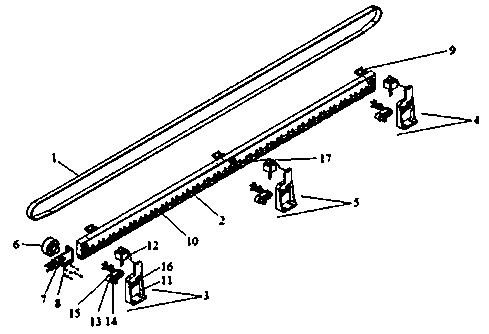
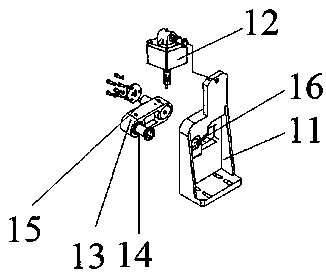
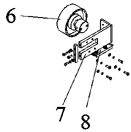
[0025] The following will clearly and completely describe the technical solutions in the embodiments of the present invention in conjunction with the accompanying drawings in the embodiments of the present invention. Obviously, the described embodiments are only a part of the embodiments of the present invention, rather than all the embodiments. The embodiments of the present invention, and all other embodiments obtained by those of ordinary skill in the art without creative work, fall within the protection scope of the present invention.

[0026] In the description of the present invention, it should be noted that the terms "top", "bottom", "one side", "the other side", "front", "rear", "middle part", "inner", " The orientation or positional relationship indicated by the “top” and “bottom” are based on the orientation or positional relationship shown in the drawings, which is only for the convenience of describing the present invention and simplifying the description, and does no...


PUM


Abstract

The invention discloses a pressing beam and upper movable wheel combination device of a ceramic edge grinding chamfering machine. The device comprises a pressing beam synchronous belt, a pressing beam, a first rotating arm mechanism, a second rotating arm mechanism and a third rotating arm mechanism. The pressing beam is arranged on the inner side of the pressing beam synchronous belt, the two ends and the middle of the pressing beam are provided with the first rotating arm mechanism, the second rotating arm mechanism and the third rotating arm mechanism correspondingly, the two ends of the pressing beam are fixedly connected with upper movable wheel mounting bases through bolts, upper movable wheels are arranged on the two ends of the inner side of the pressing beam synchronous belt, andthe upper movable wheels on the two sides are clamped on the upper movable wheel mounting bases. According to the pressing beam and upper movable wheel combination device of the ceramic edge grindingchamfering machine, the upper movable wheel assembly and the pressing beam are mounted together, and a whole body is formed. When tile stacking appears in the pressing beam tile inlet position, tileslift the upper movable wheel assembly and the pressing beam upwards, the rotating arm bearing tension fracture of the upper movable wheel assembly can be avoided, and the pressing beam synchronous belt and the lower synchronous belt can be protected against damage by pressing of the tiles.

Description

Technical field [0001] The invention relates to the field of ceramic deep processing equipment, in particular to a pressure beam of a ceramic edging chamfering machine and an upper movable wheel assembly device. Background technique [0002] 1. The upper movable wheel assembly of the existing ceramic edging full-angle machine is installed on the front rotating arm support, and is integrated with the front rotating arm support. When bricks are piled up when the pressure beam enters the brick position, because the upper movable wheel cannot float upward, at this time, the upper movable wheel assembly may break the support of the front rotating arm. [0003] 2. One end of the pressure beam timing belt meshes with the main drive synchronization wheel, and one end meshes with the upper movable wheel. When the timing belt of the pressure beam part is offset, the front and rear ends of the pressure beam timing belt cannot be with the pressure beam. When the synchronous belt is shifted sy...

Claims


Application Information

Patent Timeline
Patent Type & Authority Applications(China)
IPC IPC(8): B24B9/06B24B41/02B24B47/22
CPCB24B9/06B24B41/02B24B47/22
Inventor 何君应春明
Owner 江西一本机械设备有限公司
Why Eureka
Try Eureka