
Static pressure supporting and guiding hydraulic cylinder

A static pressure support and hydraulic cylinder technology, applied in the field of hydraulic cylinders, can solve problems affecting installation and use effects, impact vibration, noise, etc., and achieve the effect of reducing the effect of stable support

Active Publication Date: 2020-02-14
烟台星辉劳斯堡液压机械有限公司
View PDF5 Cites 0 Cited by
  • Summary
  • Abstract
  • Description
  • Claims
  • Application Information

AI Technical Summary

Problems solved by technology

[0004] When the existing hydraulic cylinder is in use, if the hydraulic rod of the hydraulic cylinder is connected to the connected part, it only needs to be reciprocated in the horizontal or vertical direction of the connected part, and the rotating device can drive the cylinder body and the hydraulic rod to rotate synchronously In some occasions, since there is no rotation limit device between the hydraulic rod and the cylinder body, the phenomenon of separation and rotation of the hydraulic rod or the cylinder body will occur, which will affect the installation and use effect of the hydraulic cylinder body on the connected parts;
[0005] At the same time, often the terminal of the hydraulic rod can reach a higher speed. Under the action of inertial force and hydraulic pressure, it will have a mechanical collision with the bottom of the cylinder, resulting in shock vibration and noise, which will adversely affect the entire hydraulic system and reduce its own use. life

Method used


Image

  • Static pressure supporting and guiding hydraulic cylinder
  • Static pressure supporting and guiding hydraulic cylinder
  • Static pressure supporting and guiding hydraulic cylinder

Examples


Embodiment Construction

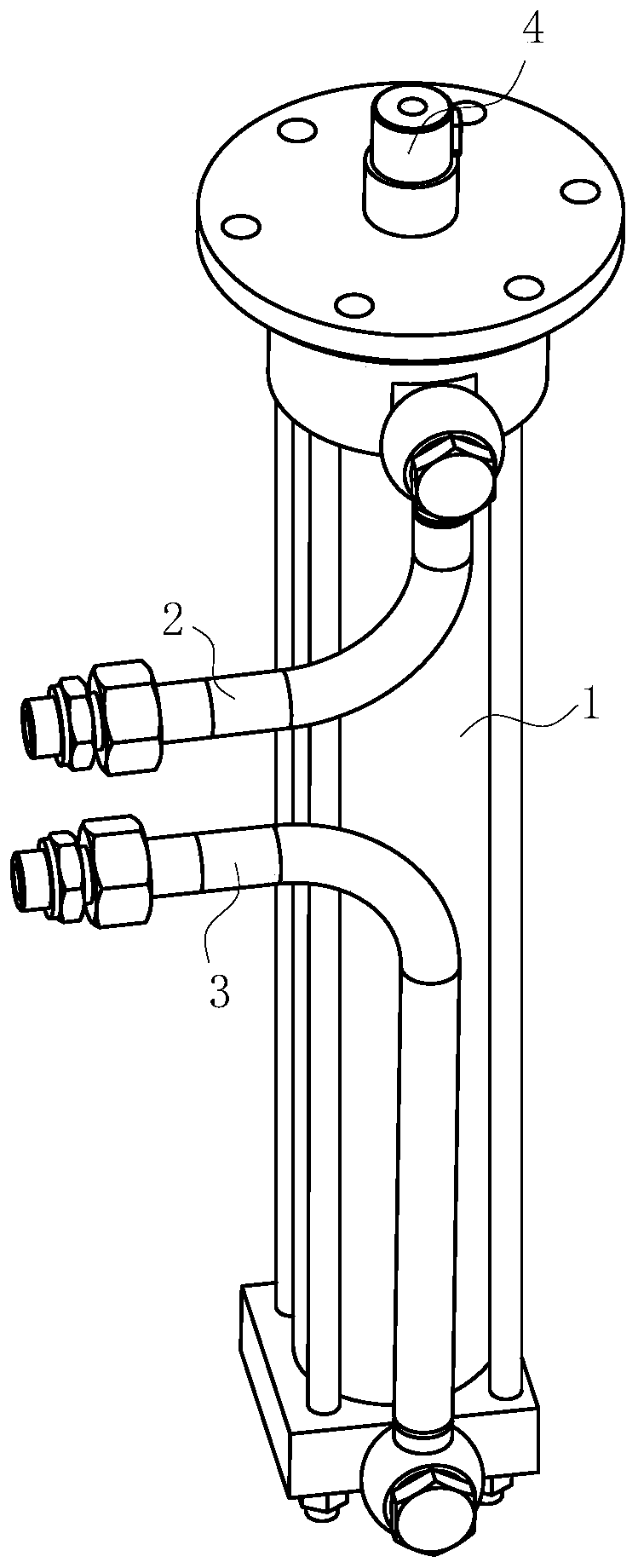
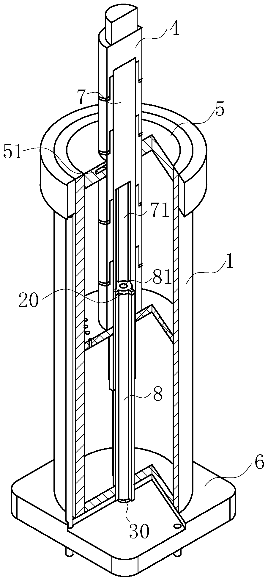
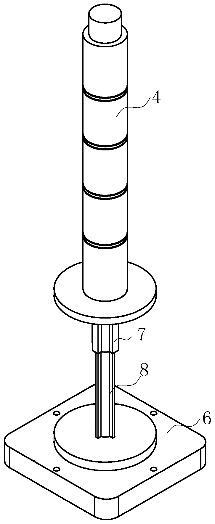
[0022] use Figure 1-Figure 4 A static pressure support guide hydraulic cylinder according to an embodiment of the present invention will be described as follows.

[0023] Such as Figure 1-Figure 4 As shown, a hydrostatic support and guide hydraulic cylinder according to the present invention includes a cylinder block 1, an upper oil pipe 2 and a lower oil pipe 3; the upper and lower ends of the cylinder body 1 are installed with an upper oil pipe 2 and a lower oil pipe 3, and An oil chamber 11 is opened in the cylinder block 1; a hydraulic rod 4 is slidably provided in the oil chamber 11, and a sealing plug is provided at the bottom end of the hydraulic rod 4; an upper end cover 5 is provided at the upper end of the cylinder block 1, and the cylinder block A lower end cover 6 is installed at the lower end of 1; both the sealing plug and the upper end cover 5 are provided with damping holes 51 for hydrostatic support; the vertical direction of the piston rod is provided with a cr...


PUM


Abstract

The invention belongs to the technical field of hydraulic cylinders, and particularly relates to a static pressure supporting and guiding hydraulic cylinder. The static pressure supporting and guidinghydraulic cylinder comprises a cylinder body, wherein an upper oil pipe and a lower oil pipe are mounted at the upper end and the lower end of the cylinder body, and an oil cavity is formed in the cylinder body; a hydraulic rod is slidably arranged in the oil cavity, and a sealing plug is arranged at the bottom end of the hydraulic rod; an upper end cover is arranged at the upper end of the cylinder body, and a lower end cover is mounted at the lower end of the cylinder body; damping holes for static pressure supporting are formed in the sealing plug and the upper end cover correspondingly; across-shaped guiding groove is formed in the vertical direction of a piston rod, and a cross-shaped guiding strip is fixedly inserted in the cross-shaped guiding groove; a cross-shaped sliding cavityis formed in the vertical direction of the cross-shaped guiding strip, and a guiding sliding rod is slidably inserted in the cross-shaped sliding cavity; the bottom end of the guiding sliding rod isfixed to the lower end cover; the hydraulic rod is formed by splicing a plurality of guiding columns; and the guiding sliding rod can play a role in axial rotation limiting on the cross-shaped guidingstrip, and thus the extending hydraulic rod can only slide in the cylinder body in a reciprocating mode and cannot axially rotate in the cylinder body.

Description

Technical field [0001] The invention belongs to the technical field of hydraulic cylinders, and specifically is a hydrostatic support and guide hydraulic cylinder. Background technique [0002] Compression transmission and its control technology are widely used in the machinery industry due to their unique advantages. Hydraulic cylinders are the most commonly used components in hydraulic technology to achieve reciprocating motion. [0003] The hydraulic cylinder is a widely used industrial automation device. Its structure is generally to install a guide sleeve in the cylinder, and then install the piston and piston rod in the guide sleeve. [0004] When the existing hydraulic cylinder is in use, if the hydraulic rod of the hydraulic cylinder is connected with the connected part, only the connecting part needs to be reciprocated horizontally or vertically, and the rotating device can drive the cylinder body and the hydraulic rod to rotate synchronously. When there is no rotation limi...

Claims


Application Information

Patent Timeline
Patent Type & Authority Applications(China)
IPC IPC(8): F15B15/14F15B15/20F15B15/22
CPCF15B15/14F15B15/1423F15B15/1433F15B15/1471F15B15/20F15B15/22
Inventor 不公告发明人
Owner 烟台星辉劳斯堡液压机械有限公司
Learn More