Vacuum transmission processing equipment and method

A technology of vacuum transmission and process equipment, which is applied in conveyor objects, transportation and packaging, and final product manufacturing, etc., can solve problems such as low production efficiency, improve operation efficiency, reduce space, and improve operation reliability and stability. Effect

Active Publication Date: 2014-04-30
KINGSTONE SEMICONDUCTOR LIMITED COMPANY
View PDF4 Cites 0 Cited by
  • Summary
  • Abstract
  • Description
  • Claims
  • Application Information

AI Technical Summary

Problems solved by technology

[0004] The technical problem to be solved by the present invention is to overcome the defect of low production efficiency of the vacuum process technology in the prior art, to provide a vacuum process with high production efficiency, more compact equipment structure, less difficulty in mechanical design, and higher reliability of equipment operation. High vacuum transmission process equipment and corresponding vacuum transmission process method

Method used


Image

  • Vacuum transmission processing equipment and method
  • Vacuum transmission processing equipment and method
  • Vacuum transmission processing equipment and method

Examples


Embodiment 1

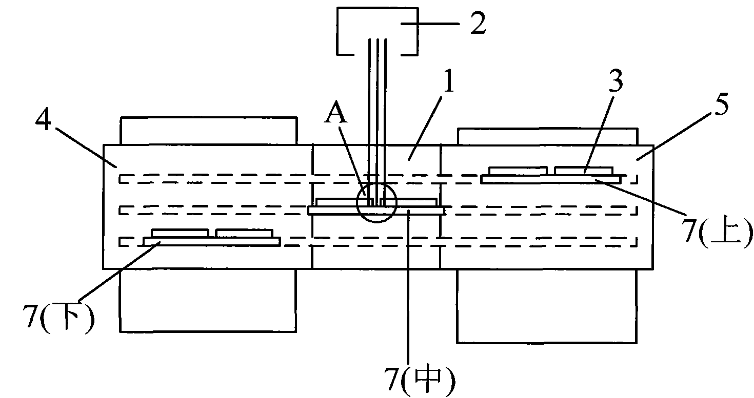
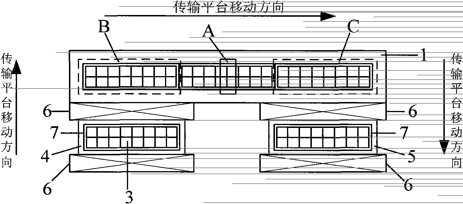
[0020] Such as figure 1 and figure 2 As shown, the vacuum transmission process equipment of the present invention first includes a vacuum process chamber 1 , and a processing device 2 is arranged in the vacuum process chamber 1 . The processing device 2 has a processing area A, and when the workpiece 3 passes through the processing area A, it will be processed by the processing device 2 . The present invention is not limited to the workpiece, for example, it may be a solar wafer. The present invention is not limited to the processing device, for example, it may be a device for processing a workpiece by ion beam or plasma, or it may be a device for heat treatment or annealing treatment of a workpiece.

[0021] One end of the vacuum process chamber 1 is provided with an inlet chamber 4 , while the other end is provided with an outlet chamber 5 . Both the inlet chamber 4 and the outlet chamber 5 can be realized by using a vacuum box with a smaller volume than the vacuum proce...

Embodiment 2

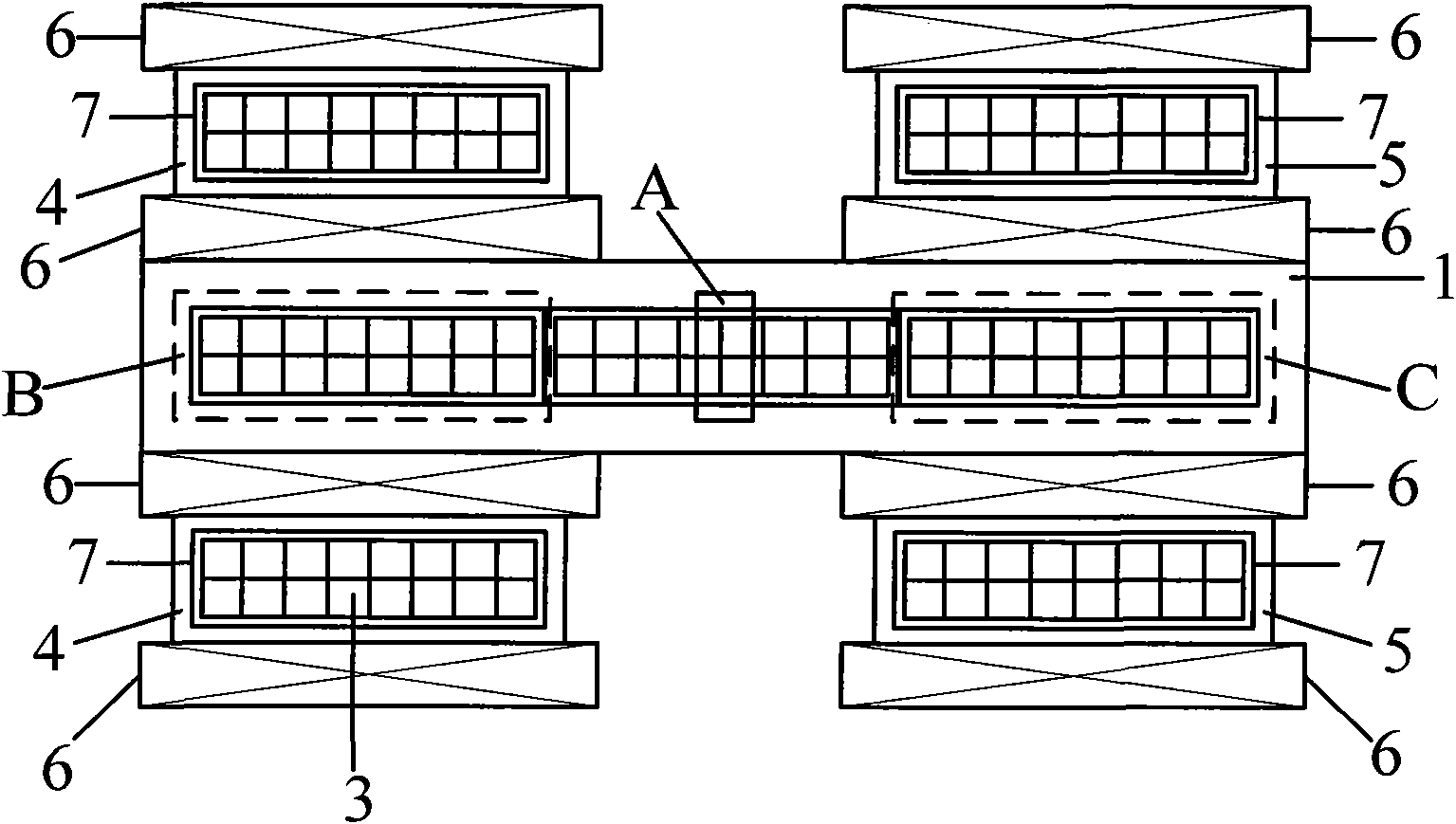
[0046] Such as image 3 As shown, in the vacuum transmission process equipment of the present invention, two above-mentioned inlet chambers 4 and / or two above-mentioned outlet chambers 5 can also be designed, wherein, the two inlet chambers can be respectively located in the vacuum process chamber 1 on both sides of one end ( image 3 The upper and lower sides of the chamber), the two output chambers can be respectively located on both sides of the other end of the vacuum process chamber 1 ( image 3 The upper and lower sides of the middle), such a design will still be able to ensure that: each transfer platform enters the vacuum process chamber 1 from any inlet chamber and enters any output chamber from the vacuum process chamber 1. The moving direction is the same as that of each transfer platform The moving direction in the vacuum process chamber 1 is vertical.

[0047]Due to the increase in the number of incoming and outgoing cavities, on the one hand, also for the purpo...

Embodiment 3

[0050] Such as Figure 4 As shown, the only difference between this embodiment and Embodiment 1 is that in this embodiment, the inlet chamber 4 and the outlet chamber 5 are collinearly arranged with respect to the vacuum process chamber 1, that is, each transfer platform is The movement direction of the entry chamber 4 into the vacuum process chamber 1 and from the vacuum process chamber 1 into the exit chamber 5 is in line with the movement direction of each transport platform in the vacuum process chamber 1 . This provides convenience for docking the two ends of the vacuum transmission process equipment with other equipment in the system, thereby facilitating the realization of an automated production line for one-way conveyance of workpieces.

[0051] To sum up, in the present invention, each transmission platform can move through the processing area successively and continuously to perform the processing process on the workpiece on it, thereby obtaining extremely high prod...


PUM


Abstract

The invention discloses vacuum transmission processing equipment and method. The equipment comprises a vacuum processing chamber; a machining device is arranged in the vacuum processing chamber and is provided with a machining area; one end of the processing chamber is provided with a feeding chamber, and the other end of the processing chamber is provided with an ejecting chamber; in the vacuum processing chamber, a first waiting area is arranged on one side of the machining area, which is close to the feeding cavity, and a second waiting area is arranged on the other side of the machining area, which is close to the ejecting chamber; the vacuum transmission processing equipment also comprises a plurality of transmission platforms; and each transmission platform is used for sequentially and continuously moving through the machining area to finish workpiece machining. According to the invention, extra-high production efficiency can be realized.

Description

technical field [0001] The invention relates to vacuum process technology, in particular to a vacuum transmission process equipment and a corresponding vacuum transmission process method. Background technique [0002] New energy is one of the five most decisive technological fields in the world's economic development in the 21st century, and solar energy is a clean, efficient and inexhaustible new energy. In the new century, governments of all countries regard the utilization of solar energy resources as an important content of the national sustainable development strategy. Photovoltaic power generation has many advantages such as safety, reliability, no noise, no pollution, less constraints, low failure rate, and easy maintenance. In recent years, with the rapid development of the international photovoltaic power generation industry, the supply of solar wafers exceeds the demand, so improving the photoelectric conversion efficiency of solar wafers and the production capacit...

Claims


Application Information

Patent Timeline
Patent Type & Authority Patents(China)
IPC IPC(8): H01L21/67H01L21/677H01L31/18
CPCY02P70/50
Inventor 桑尼·沃哈·诺奇金浩陈炯
Owner KINGSTONE SEMICONDUCTOR LIMITED COMPANY
Why Eureka
Try Eureka