Auxiliary formwork removing device for vertical column bottom formwork, and formwork removing method

A column and bottom mold technology, applied in the direction of unloading devices, manufacturing tools, etc., can solve the problems of column height, weight, high cost, and inability to demould the column, and achieve the effect of simple and fast dismantling operation and auxiliary power consumption

Active Publication Date: 2020-02-18
绍兴市城投建筑工业化制造有限公司 +1
View PDF5 Cites 3 Cited by
  • Summary
  • Abstract
  • Description
  • Claims
  • Application Information

AI Technical Summary

Problems solved by technology

[0004] The above-mentioned patent rotates the lever through the suction force of the electromagnet to shrink the inner mold, and then the pull plate of the inner mold is sucked by the electromagnet on the pull plate, and finally the motor drives the pulley and the wire rope to drag the inner mold out of the mold, and the demoulding process Simple; however, due to the high height and weight of the column, the cost of the frame corresponding to the frame is relatively high, and for the column of different heights, the frame of the corresponding height needs to be constructed during the demoulding process, and the cost of the demoulding operation is high. Therefore, it cannot be practically applied to the demoulding operation of the column

Method used


Image

  • Auxiliary formwork removing device for vertical column bottom formwork, and formwork removing method
  • Auxiliary formwork removing device for vertical column bottom formwork, and formwork removing method
  • Auxiliary formwork removing device for vertical column bottom formwork, and formwork removing method

Examples


Embodiment

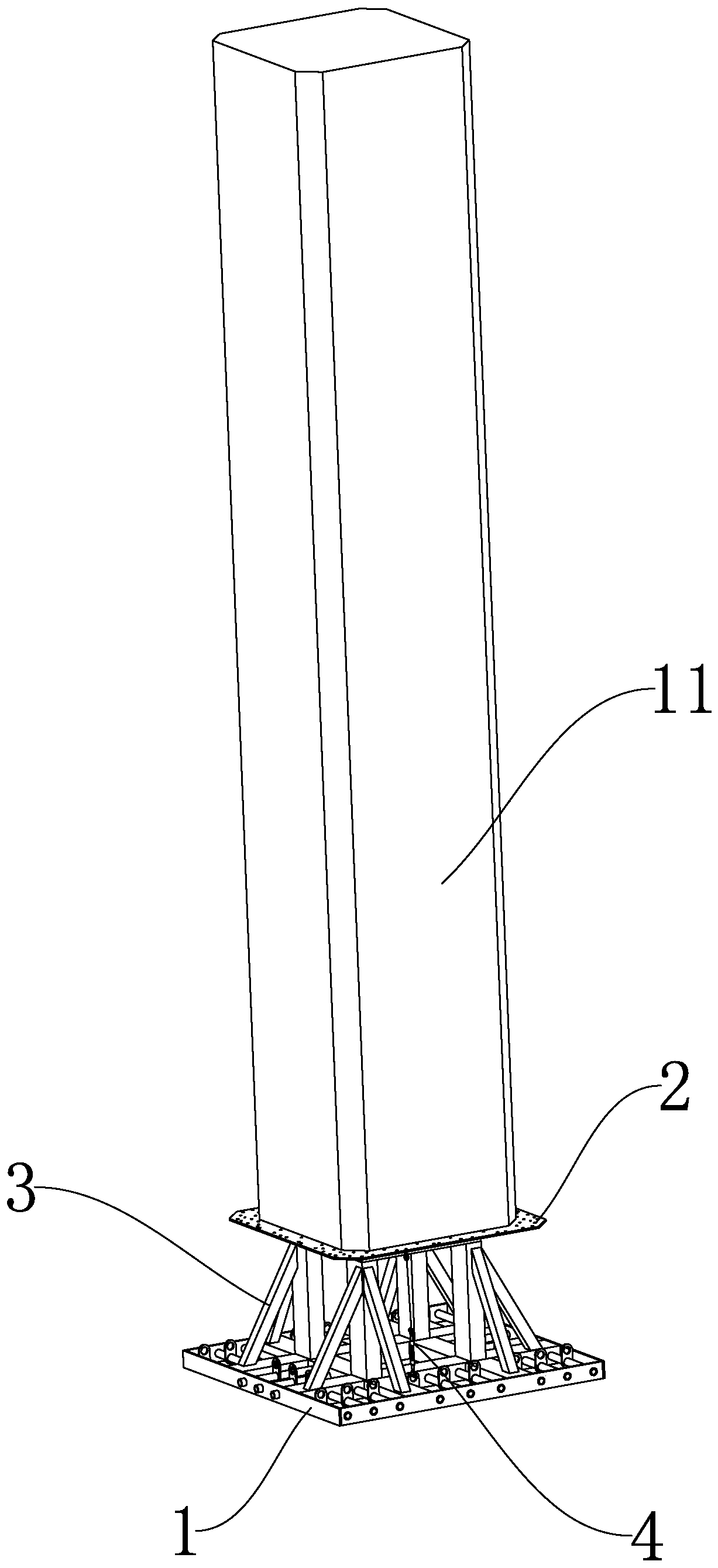
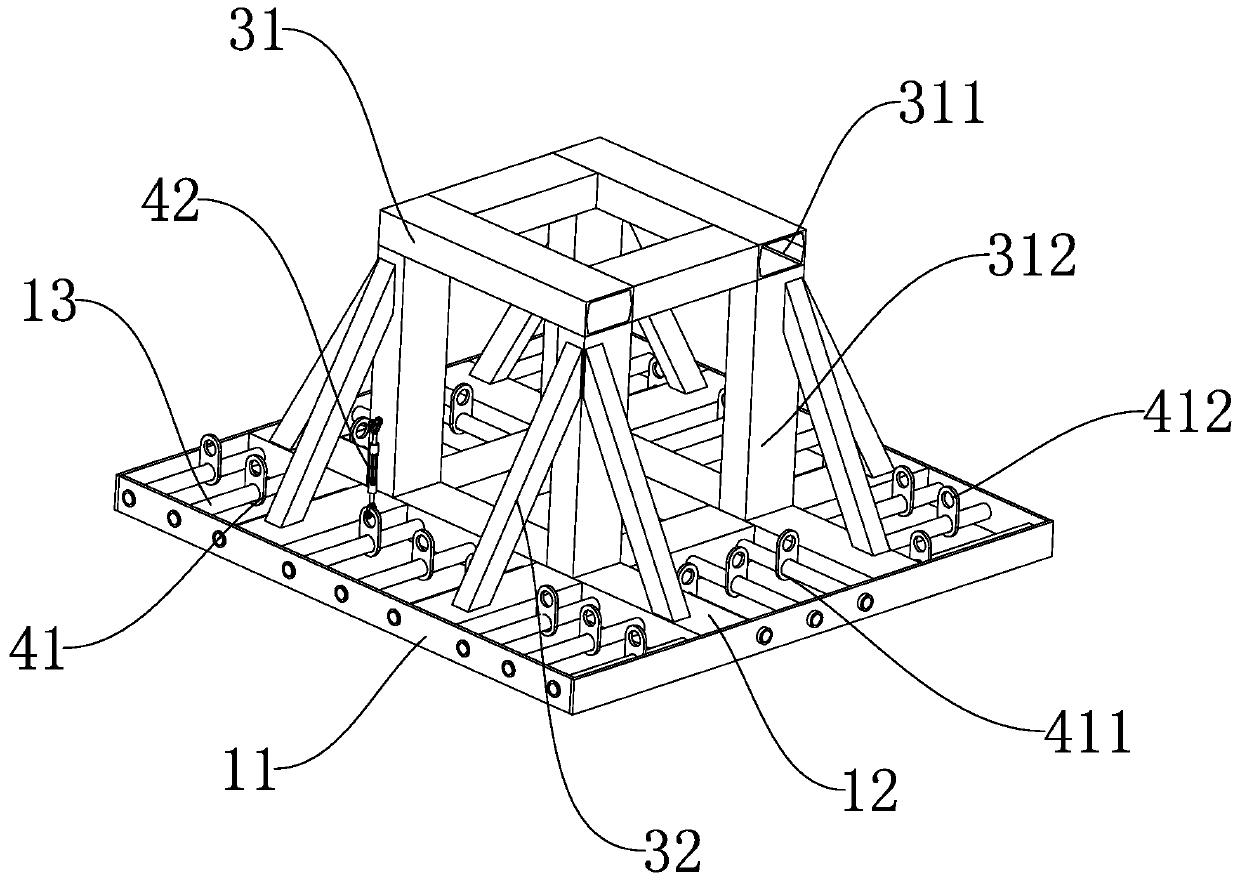
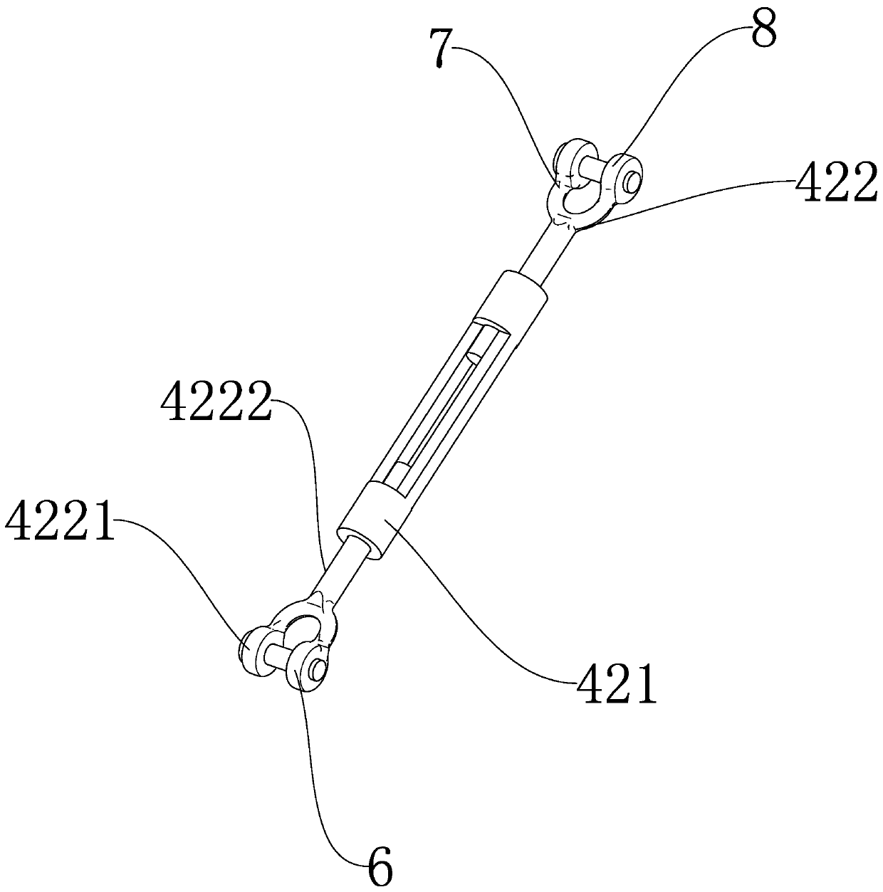
[0040] Such as Figure 1 to Figure 6 Shown, a kind of auxiliary demolition device of column base mold, comprises the fixed member 1 that is fixedly connected with ground, is characterized in that, is connected with support member 3 in order to support column base mold 2 on described fixation member, and column base form is in Under the action of the supporting member, it is separated from the ground. A pre-tensioning member 4 is provided between the bottom mold of the column and the fixed component. It can be separated from the bottom mold of the column under driving; the bottom mold of the column is in the shape of a beveled rectangular plate, and the bottom mold of the column is provided with a number of positioning holes 21 and installation holes 22 penetrating along its thickness direction. The arrangement of the positioning holes and the installation holes is rectangular. shape, the positioning hole is located on the first inner offset line 2a of the outer edge of the col...


PUM


Abstract

The invention provides an auxiliary formwork removing device for a vertical column bottom formwork, and a formwork removing method. The auxiliary formwork removing device for the vertical column bottom formwork and the formwork removing method are used for solving the technical problem that in the prior art, after a vertical column is prefabricated in a factory, a bottom formwork bonded to the bottom face of the concrete vertical column is large is formwork removing difficulty. The auxiliary formwork removing device comprises a fixing component fixedly connected with the ground, a supporting component used for supporting the vertical column bottom formwork is connected to the fixing component, the vertical column bottom formwork is separated from the ground under the effect of the supporting component, a pre-tightening component is arranged between the vertical column bottom formwork and the fixing component, the fixing component provides pre-tightening tension for the vertical columnbottom formwork through the pre-tightening component to enable the vertical column bottom formwork to be separated from the bottom face of the vertical column, and the vertical column can be separatedfrom the vertical column bottom formwork under driving of a displacement component. The auxiliary formwork removing device has the following beneficial effects that (1) compared with the prior art, aplastic film or a man-made partition plate does not need to be laid on the vertical column bottom formwork, and demounting operation of the vertical column bottom formwork is easy and quick; and (2)demounting of the vertical column bottom formwork can be achieved by selecting the displacement component with small power consumption, and the power consumption of the auxiliary formwork removing device is significantly lowered.

Description

technical field [0001] The invention relates to the technical field of mold removal and assembly, in particular to an auxiliary mold removal device and a mold removal method for a column bottom mold. Background technique [0002] With the promotion and popularization of bridge prefabricated assembly construction technology in urban bridge construction, the emergence of a large number of prefabricated columns and prefabricated cap beams has gradually standardized bridge construction. In the existing column processing, after the various data of the column are obtained, the column mold meeting the size requirements is processed in the factory, and then the column is processed by pouring the concrete mold. After the column is poured, the concrete column inside the column mold needs to be demoulded. Among them, the bottom form is closely bonded to the bottom surface of the concrete column under the action of the concrete column's own weight, so the demoulding operation of the bot...

Claims


Application Information

Patent Timeline
IPC IPC(8): B28B13/06
CPCB28B13/06
Inventor 宁英杰何智钢迟文明郭松潘森兵黄祎涵
Owner 绍兴市城投建筑工业化制造有限公司
Why Eureka
Try Eureka