Novel cement mortar stirring device

A cement mortar and mixing device technology, applied in cement mixing devices, measuring devices, clay preparation devices, etc., can solve problems such as waste of materials, impact on accuracy, unreasonable structural design, etc.

Inactive Publication Date: 2020-02-18
TAIZHOU SANYE CONCRETE CO LTD
View PDF0 Cites 0 Cited by
  • Summary
  • Abstract
  • Description
  • Claims
  • Application Information

AI Technical Summary

Problems solved by technology

[0002] The cement mortar mixing device is a kind of equipment used to stir the cement mortar mixture according to the speed and time required by the cement mortar strength inspection specification. The raw materials of the cement mortar include cement, standard sand and water. The existing cement mortar The structural design of the mortar mixing device is unreasonable. When the material is stirred, due to the large stirring range of the stirring paddle, the material is easi

Method used


Image

  • Novel cement mortar stirring device
  • Novel cement mortar stirring device
  • Novel cement mortar stirring device

Examples


Embodiment 1

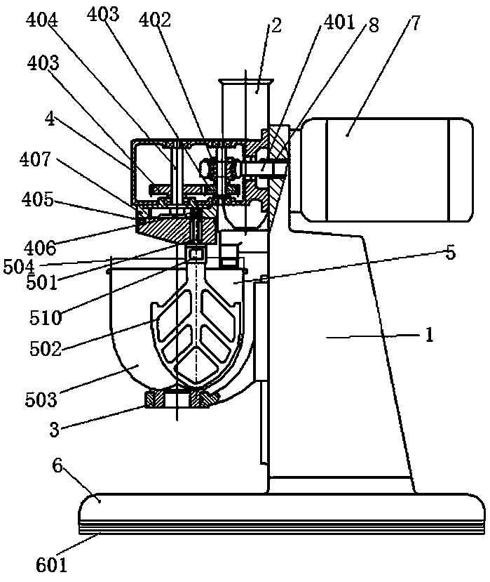
[0016] Embodiment 1: A new type of cement mortar mixing device, including a fuselage 1, a feeding box 2, a transmission box assembly 4, a stirring assembly 5 and a base 6, and the side end of the fuselage 1 is fixedly equipped with a feeding box 2, so One end of the fuselage 1 is provided with a transmission box assembly 4 , and the bottom end of the transmission box assembly 4 is provided with a stirring assembly 5 and is in transmission connection with it. The fuselage 1 is arranged on a base 6 .

Embodiment 2

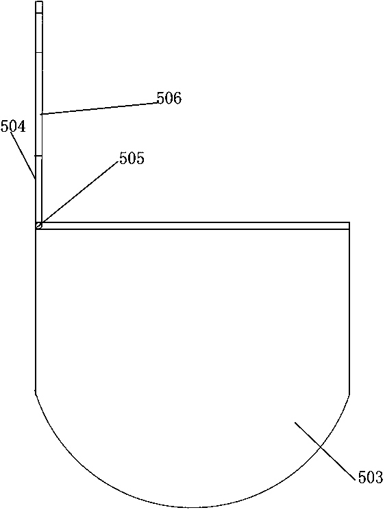
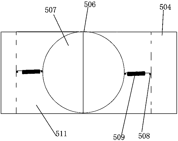
[0017] Embodiment 2: the stirring assembly 5 includes a stirring shaft 501, a stirring paddle 502 and a stirring box 503, the bottom end of the stirring shaft 501 is equipped with a stirring paddle 502, and the upper end of the stirring box 503 is communicated with the charging box 2 through a delivery pipeline, The mixing box 503 is equipped with a protective box cover 504, the mixing box 503 is located on the support 3, the protective box cover 504 is closed and connected with the mixing box 503 through a pin 505, and the protective box cover 504 is opened There is a relief hole 506, the relief hole 506 is equipped with a relief clip cover 507, the two sides of the relief hole 506 are provided with cavity grooves 511, and the side ends of the protective case cover 504 and the inner wall of the cavity groove 511 are both A positioning hook 508 is installed, and a telescopic spring 509 runs through the positioning hook 508 and is hooked to it. The stirring shaft 501 is equipped...

Embodiment 3

[0018] Embodiment 3: An anti-slip layer 601 is installed at the bottom of the base 6, and the anti-slip layer 601 is integrally formed by injection molding of polyurethane rubber. The rest of the technical solutions are the same as those in Embodiments 1 and 2.


PUM


Abstract

The invention discloses a novel cement mortar stirring device. The novel cement mortar stirring device comprises a machine body, a feeding box, a transmission box assembly, a stirring assembly and a base, wherein the feeding box is fixedly arranged at the side end of the machine body; the transmission box assembly is arranged at one end of the machine body; the stirring assembly is arranged at thebottom of the transmission box assembly and is in transmission connection with the transmission box assembly; the machine body is arranged on the base; an anti-slipping layer is arranged at the bottom of the base. According to the novel cement mortar stirring device, materials can be effectively prevented from overflowing from a stirring box when stirred by a stirring paddle, so that waste of thematerials is avoided and a test result is guaranteed; a protection box cover is in closed connection with the stirring box through a hinge pin, and thus the stirring box is easily opened and closed and also easily cleaned after a test is completed; the stirring paddle is used for extruding two symmetrical avoiding clamping covers so that the avoiding clamping covers and retractable springs are retracted inwards; when a stirring shaft is located between the avoiding clamping covers, the avoiding clamping covers and the retractable springs can extend outwards to clamp the stirring shaft, so that the protection box cover is easily opened; moreover, the stirring shaft and the stirring paddle can enter the stirring box, and the novel cement mortar stirring device is simple and convenient to mount.

Description

technical field [0001] The invention relates to the technical field of inspection equipment, in particular to a novel cement mortar mixing device. Background technique [0002] The cement mortar mixing device is a kind of equipment used to stir the cement mortar mixture according to the speed and time required by the cement mortar strength inspection specification. The raw materials of the cement mortar include cement, standard sand and water. The existing cement mortar The structural design of the mortar mixing device is unreasonable. When the material is stirred, due to the large stirring range of the stirring paddle, the material is easily overflowed from the mixing box, resulting in waste of material, which has a certain impact on the accuracy of the test. The above problems can be solved by installing a box cover on the mixing box, but the installation of the box cover will cause the stirring paddle to be unable to enter the box body, and the box cover must be opened to...

Claims


Application Information

Patent Timeline
IPC IPC(8): B28C5/16B28C5/08G01N1/28
CPCB28C5/0806B28C5/0812B28C5/0831B28C5/0856B28C5/16G01N1/286
Inventor 张秧林
Owner TAIZHOU SANYE CONCRETE CO LTD
Why Eureka
Try Eureka