
Dredging device for water conservancy construction

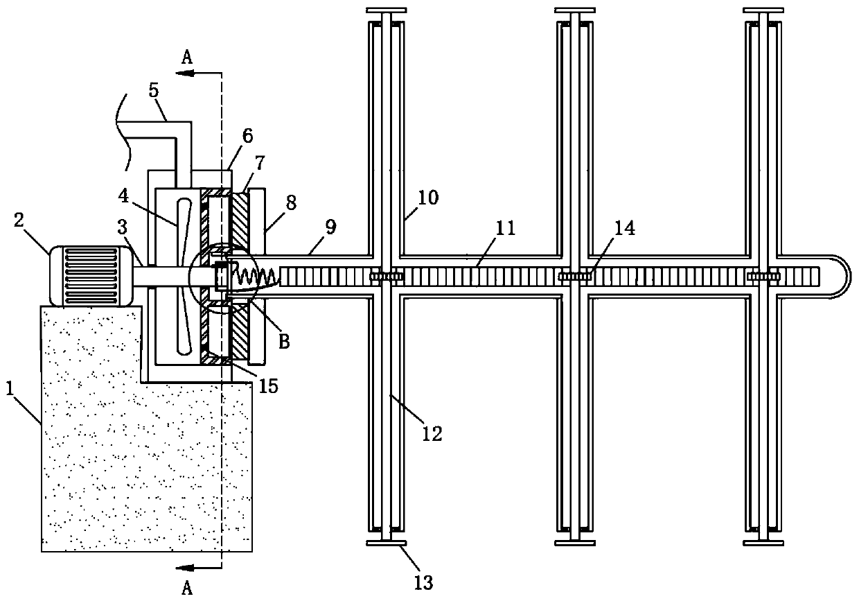
A water conservancy and water storage tank technology, which is applied in water conservancy projects, water supply devices, water conservancy engineering equipment, etc., can solve the problems of high economic cost of equipment, poor dredging effect, and difficult scraping, so as to save economic costs and Rich power and cleaning means, better cleaning effect

Active Publication Date: 2020-02-18
王莉
View PDF7 Cites 5 Cited by
  • Summary
  • Abstract
  • Description
  • Claims
  • Application Information

AI Technical Summary

Problems solved by technology

[0003] 1. The drive of the existing dredging device requires not only the motor, but also the water pump to pump water into the pipeline, which makes the equipment of the whole device too complicated and difficult to transport, and also makes the economic cost of the whole equipment higher. The motor and water pump At the same time, it also needs to consume too much power;
[0004] 2. The existing dredging devices are generally driven by a motor to drive the rotating shaft to rotate, and then drive some cleaning mechanisms to rotate to dredge the inner wall of the pipeline. However, during the construction of water conservancy projects, many debris such as cement adhere On the inner wall of the pipeline, these sundries are difficult to scrape off only by this single rotation, and the dredging effect is not good.

Method used


Image

  • Dredging device for water conservancy construction
  • Dredging device for water conservancy construction
  • Dredging device for water conservancy construction

Examples


Embodiment Construction

[0018] The following will clearly and completely describe the technical solutions in the embodiments of the present invention with reference to the accompanying drawings in the embodiments of the present invention. Obviously, the described embodiments are only some, not all, embodiments of the present invention.

[0019] In describing the present invention, it should be understood that the terms "upper", "lower", "front", "rear", "left", "right", "top", "bottom", "inner", " The orientation or positional relationship indicated by "outside", etc. is based on the orientation or positional relationship shown in the drawings, and is only for the convenience of describing the present invention and simplifying the description, rather than indicating or implying that the referred device or element must have a specific orientation, so as to Specific orientation configurations and operations, therefore, are not to be construed as limitations on the invention.

[0020] refer to Figure ...


PUM


Abstract

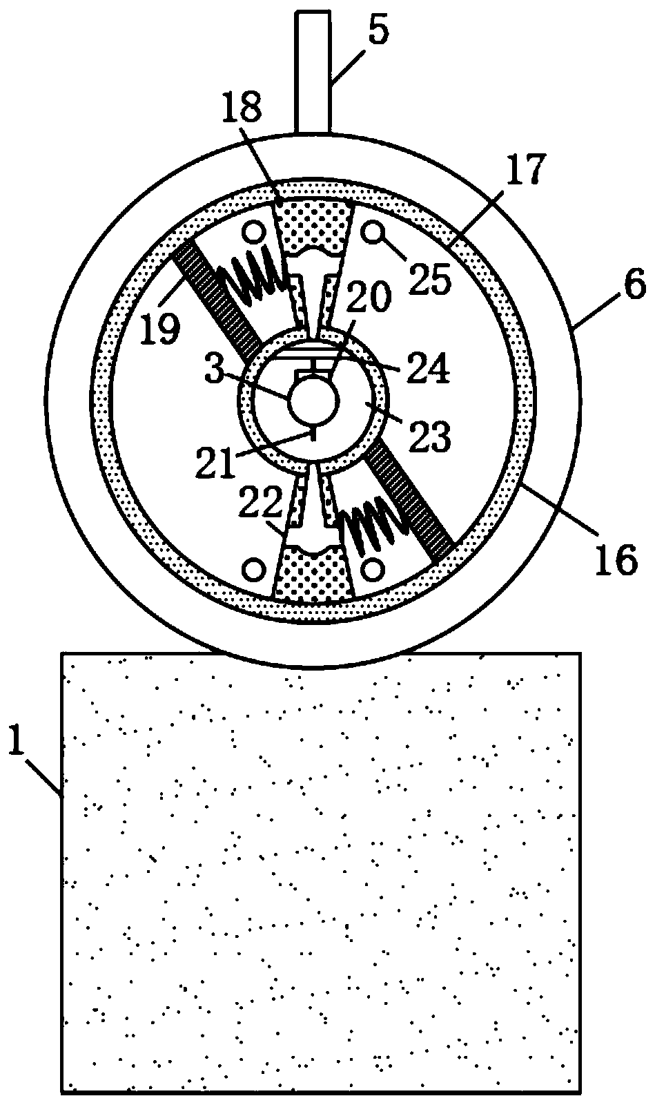
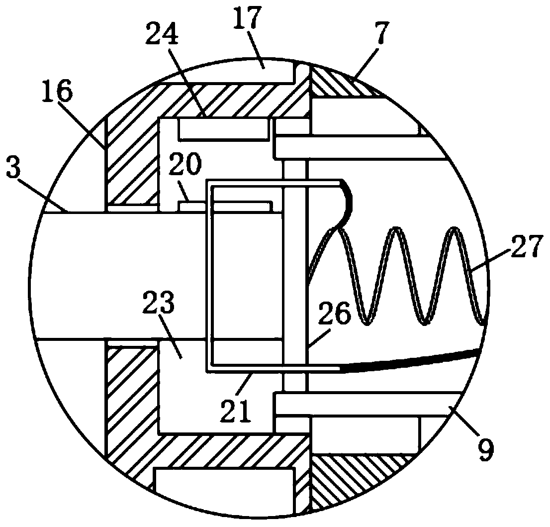
The invention discloses a dredging device for water conservancy construction. The dredging device comprises a support column. A driving motor is fixedly arranged on the upper wall of the support column. The upper wall of the support column is fixedly connected with a water storage tank. A water inlet pipe is arranged on the upper wall of the water storage tank in a communicated manner. A water absorbing mechanism is arranged in the water storage tank. The water absorbing mechanism comprises a water absorbing disc fixedly connected to the inner wall of the water storage tank. An annular cavityis formed in the water absorbing disc. A circular groove is formed in the side wall, far away from one end of the driving motor, of the water absorbing disc. Two stop blocks are symmetrically arrangedin and fixedly connected with the interior of the annular cavity. The interiors of the two stop blocks are communicated with the circular groove through one-way channels. The side walls of the two stop blocks are elastically connected with magnetic sliding plugs through reset springs. Water inlets are correspondingly formed in the inner walls, close to the two sides of the two baffles, of the annular cavity. One-way valves are correspondingly arranged in the four water inlets. By the adoption of the dredging device for water conservancy construction, the transportation difficulty of the device is reduced, the economic cost and the electric energy are saved, the more abundant cleaning means is provided, and the cleaning effect is better.

Description

technical field [0001] The invention relates to the technical field of water conservancy construction, in particular to a dredging device for water conservancy construction. Background technique [0002] Now, my country's water conservancy construction is becoming more and more developed. By building water conservancy projects, controlling water flow and preventing floods, it has brought great protection to people's happy life. In water conservancy projects, it is usually necessary to use some water conservancy pipelines. During the use of water conservancy pipelines, the pipeline mouth is often blocked due to the accumulation of some sundries and silt, which brings great inconvenience to the smooth implementation of water conservancy projects. Therefore, it is necessary to periodically clean the silt at the pipeline mouth Desilting and dredging the debris attached to the inner wall of the pipeline, thereby preventing the blockage of the pipeline. However, the existing dredgin...

Claims


Application Information

Patent Timeline
IPC IPC(8): E03F9/00E02B1/00
CPCE02B1/00E03F9/005
Inventor 张亚鑫
Owner 王莉
Learn More