Fixed-point gas outlet method

An air outlet device and air pill technology, applied in electrical components, spark gaps, spark gap parts, etc., can solve the problem of poor arc extinguishing effect, achieve the effect of arc extinguishing effect, improve safety capability, and fast response time

Active Publication Date: 2020-02-18
GUANGXI UNIV +1
View PDF4 Cites 0 Cited by
  • Summary
  • Abstract
  • Description
  • Claims
  • Application Information

AI Technical Summary

Problems solved by technology

[0005] The purpose of the present invention is to provide a fixed-point gas outlet method to solve the technical problem that the arc extinguishing effect of the existing gas generating device is not good

Method used


Image

  • Fixed-point gas outlet method
  • Fixed-point gas outlet method
  • Fixed-point gas outlet method

Examples


Embodiment 1

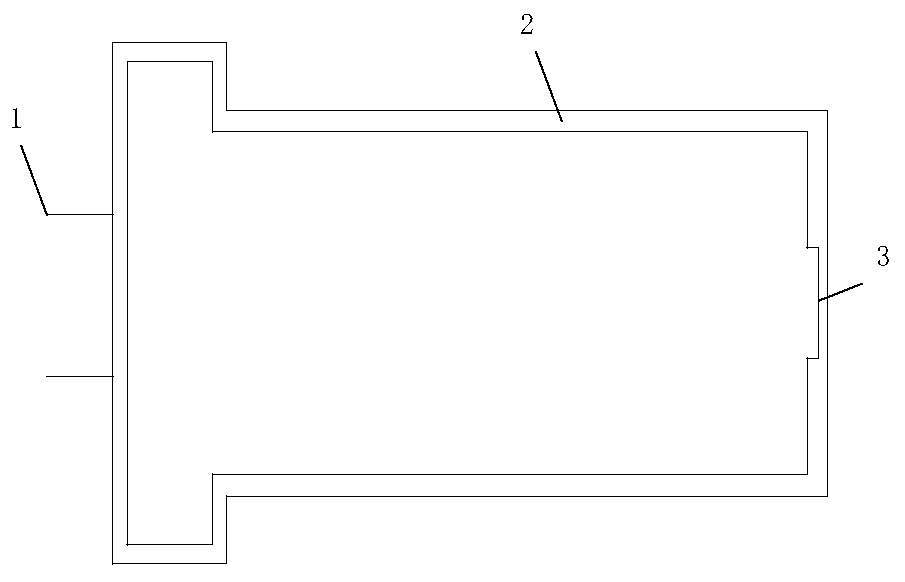
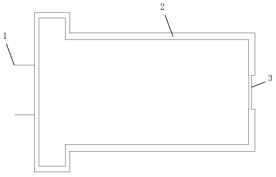
[0034] Such as figure 1 , 2 As shown, the thickness of the steel shell 2 is evenly distributed in other parts, but a directional gas outlet portion 3 is provided at the bottom of the gas pill, and the thickness of the steel shell 2 at this place is relatively thin, so that the gas produced after the gas-producing fuel is burned The gas is ejected directionally from the weak point of the gas outlet. The air outlet part is located at the bottom of the air pill, which is round in shape with a diameter of about 5-6mm. The outside of the steel shell at the air outlet is flush with the periphery, and the inside of the steel shell at the air outlet is lower than the periphery.

Embodiment 2

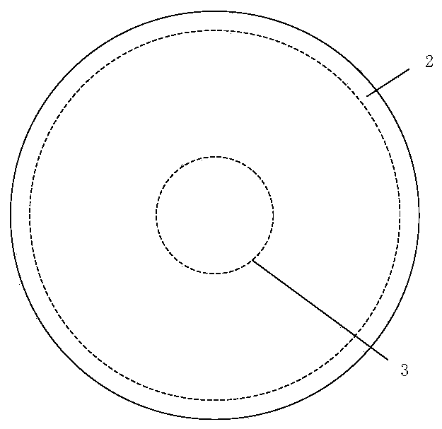
[0036] Such as image 3 , 4As shown, the thickness of the steel shell 2 is evenly distributed in other parts, but a directional gas outlet part 3 is provided at the bottom of the gas pill, and the thickness of the steel shell at this place is relatively thin, so that the gas produced after the combustion of the gas-producing fuel is released from the The weak point of the air outlet is directed to spray. The air outlet part is located at the bottom of the air pill, which is round in shape with a diameter of about 5-6mm. The outer side of the steel shell at the air outlet is lower than the periphery, and the inner side of the steel shell at the air outlet is flush with the periphery.

Embodiment 3

[0038] Such as Figure 5 , 6 As shown, the air outlet at the bottom of the steel shell is a through hole, the through hole is circular, and the inner diameter is about 5-6mm. A directional bucket 5 protrudes downwards from the through hole at the bottom of the steel shell, and the length of the directional bucket is about 5-8mm. A circular aluminum plate 4 is designed at the bottom of the air pill and inside the steel shell. The diameter of the aluminum plate 4 is the same as the inner diameter of the steel shell, and the thickness of the aluminum plate is about 2-5mm. The connection between the aluminum plate 4 and the steel shell can be pressed or welded. A sealed space is formed, and gas-producing fuel is placed inside the sealed space.


PUM


Abstract

The invention discloses a fixed-point gas outlet method, and belongs to the technical field of power system lightning protection. A fixed-point gas outlet device is arranged. The fixed-point gas outlet device comprises a steel shell. A gas-producing fuel is placed in the steel shell. One end of the steel shell is provided with a trigger pin. The trigger pin penetrates through the steel shell to contact with the gas-producing material in the steel shell. The other end of the steel shell is provided with a gas outlet part. The shell at the gas outlet part is thinner than the shell at other partsof the steel shell. The wrapping strength of the steel shell is greater than the maximum atmospheric pressure of the gas-producing material. The lightning trigger signal contacts the gas-producing material after passing through the trigger pin. The gas-producing material in the steel shell instantly burns to generate arc-extinguishing gas. The arc-extinguishing gas breaks through the shell at thegas outlet part, and the arc-extinguishing gas ejects out from the gas outlet part to extinguish the arc. The method can improve the safety capability of the solid phase arc extinguishing lightning protection device without damaging the external structure under the condition that the external structure is not strengthened.

Description

technical field [0001] The invention relates to the technical field of electric power system lightning protection, in particular to a fixed-point gas outlet method. Background technique [0002] Lightning protection of transmission lines has always been an important part of the lightning protection work of the power sector, and lightning faults are still one of the important factors affecting the safety of the power grid. Lightning strikes on transmission lines cause flashover of line insulators, and the resulting power frequency freewheeling damages insulator strings and fittings, resulting in burnt insulator strings and wire burnout accidents. [0003] Existing lightning protection devices for transmission lines mainly use transmission line lightning protection gap devices, but the key to lightning protection used in existing lightning protection gap devices is to use gas generators for arc extinguishing treatment. However, the arc extinguishing effect of the existing gas...

Claims


Application Information

Patent Timeline
Patent Type & Authority Applications(China)
IPC IPC(8): H01T1/10
CPCH01T1/10
Inventor 王嬿蕾王锟张清河徐宇恒彭斐黄萍李继强王国锋王巨丰李冠华
Owner GUANGXI UNIV
Why Eureka
Try Eureka