Recoverable filter and filter pushing device

A filter and push rod technology, applied in the field of medical devices, can solve the problems of difficult recovery, filter displacement, inferior vena cava penetration, etc.

Active Publication Date: 2020-02-21
APT MEDICAL HUNAN INC
View PDF23 Cites 0 Cited by
  • Summary
  • Abstract
  • Description
  • Claims
  • Application Information

AI Technical Summary

Problems solved by technology

The removal rate of retrievable vena cava filters only accounted for 48% (from 11% to 100%) of the total number of filters inserted, and the lower removal rate of retrievable vena cava filters was mainly related to the following factors: In order to facilitate recovery, the retrievable vena cava Filters need to be designed with features such as soft hooks, collapsed components, and unconstrained stents, but these features can lead to unwanted filter migration, tilting, deployment difficulties / failures, retrieval difficulties, inferior vena cava penetration, etc., which are undesirable Events increase the difficulty of filter recycling, which can cause life-threatening to patients; as of 2016, 2006 cases of adverse events were reported to the US FDA, including 253 cases of filter / fragment shedding, 215 cases of filter / fragment migration, and deployment difficulty / failure 213 Cases, 154 cases of difficult removal, 118 cases of material perforation, 95 cases of filter tilt, and filter breakage, expansion failure and some unexplained adverse events, etc.

Method used


Image

  • Recoverable filter and filter pushing device
  • Recoverable filter and filter pushing device
  • Recoverable filter and filter pushing device

Examples


Embodiment 1

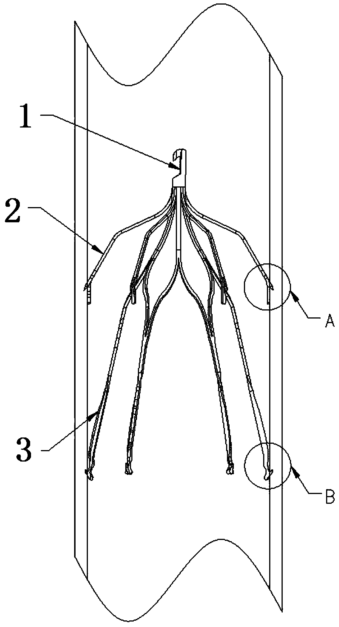
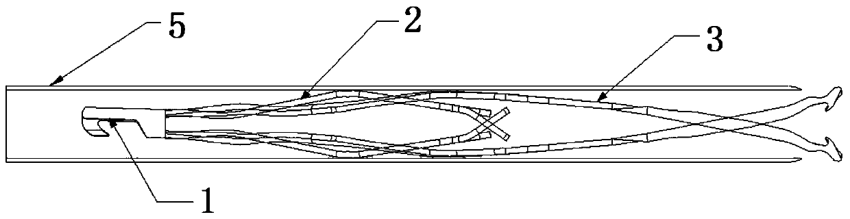
[0085] A recyclable filter, including: a recovery hook 1, a plurality of upper pillars 2, a plurality of lower pillars 3

[0086] One end of the upper pillar 2 and the lower pillar 3 is respectively connected to the recovery hook 1, and the other end extends obliquely along the circumferential direction of the recovery hook 1, and the upper pillar 2 and the lower pillar 3 different inclinations;

[0087] The ends of the upper strut 2 and the lower strut 3 away from the recovery hook 1 are respectively provided with an upper hook 21 and a lower hook 31 for fixing to the blood vessel wall;

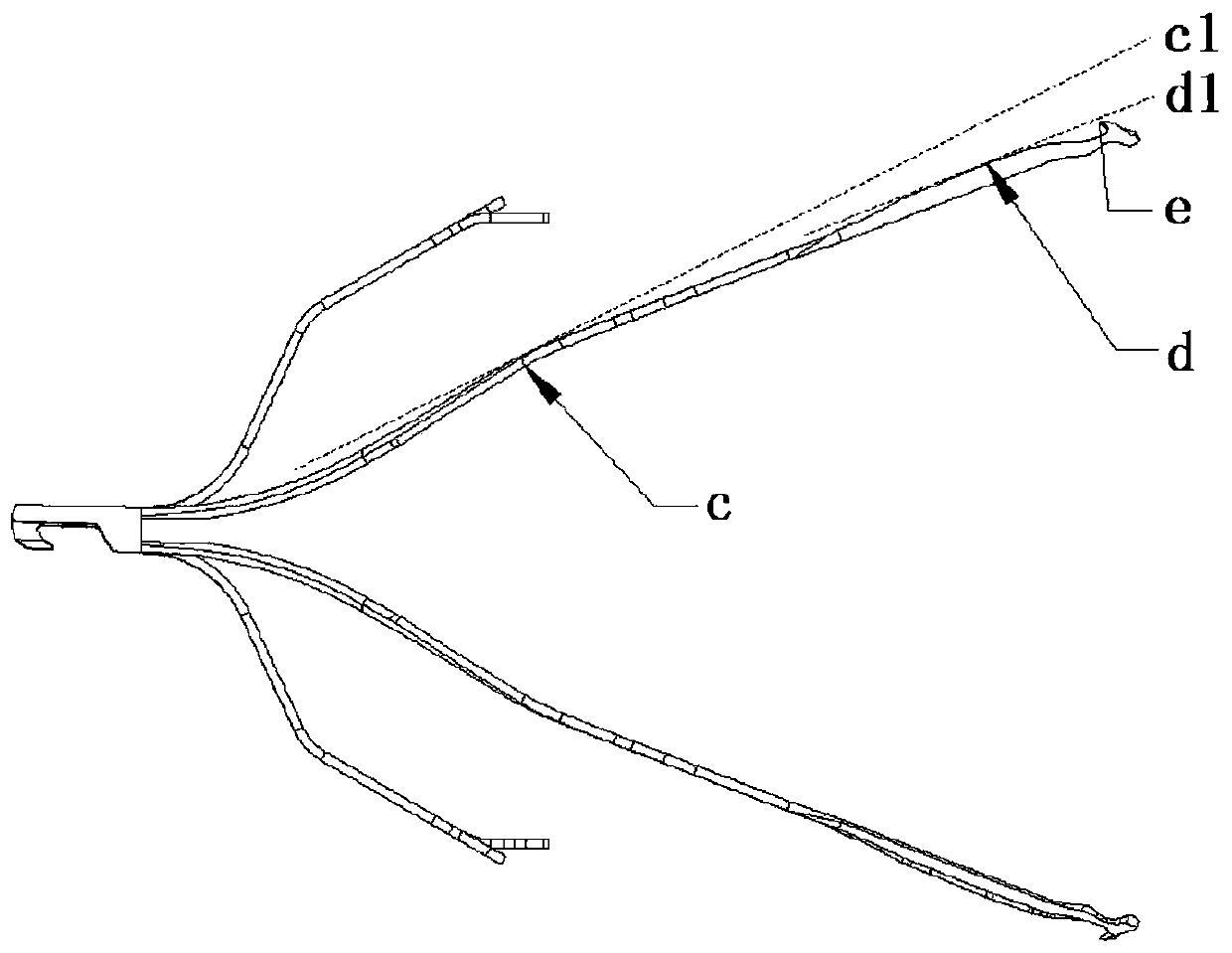
[0088] The lower pillar 3 is provided with a recovery structure that facilitates the recovery of the recyclable filter, so that during recovery, the apex of the lower hook 31 is located below the tangent plane of the highest point of the lower pillar 3;

[0089] A groove 32 is provided on the side of the lower strut 3 close to the lower hook 31 , so that when the retrievable filter is deplo...


PUM


Abstract

The application discloses a recoverable filter. The recoverable filter comprises a recovering hook, a plurality of upper layer supporting columns and a plurality of lower layer supporting columns, wherein one ends of the upper layer supporting columns and one ends of the lower layer supporting columns are respectively connected with the recovering hook, the other ends of the upper layer supportingcolumns and the other ends of the lower layer supporting columns respectively incline and extend along the circumferential direction of the recovering hook, and the inclination degrees of the upper layer supporting columns are different from those of the lower layer supporting columns; upper layer stab hooks for being fixed to vascular walls are respectively arranged at one ends, away from the recovering hook, of the upper layer supporting columns, and lower layer stab hooks for being fixed to the vascular walls are respectively arranged at one ends, away from the recovering hook, of the lower layer supporting columns; the lower layer supporting columns are provided with a recovering structure which is convenient for the recoverable filter to recover, so that when the recoverable filter is recovered, the peaks of the lower layer stab hooks are located under the sections of highest points of the lower layer supporting columns; and a groove is formed in one side, close to the lower layer stab hooks, of each lower layer supporting column, so that when the recoverable filter is unfolded, the lower layer stab hooks can penetrate into the vascular walls. The application further providesa filter conveying device. Through the adoption of the recoverable filter provided by the application, the filter can be smoothly recovered.

Description

technical field [0001] The present application relates to the technical field of medical devices, in particular to a retrievable filter and a filter pushing device. Background technique [0002] The vena cava filter is a filtering device designed to prevent pulmonary embolism caused by emboli in the inferior vena cava system. Three types of vena cava filters have appeared in the market successively, namely permanent, temporary and optional recyclable vena cava filters. Permanent vena cava filters reduce the incidence of fatal pulmonary thromboembolism (PTE), but over time increase the risk of recurrent deep vein thrombosis (DVT) and may lead to inferior vena cava embolism and a A series of complications, including filter perforation, detachment, migration, and filter fracture, can pose a permanent threat to the patient. [0003] In order to solve the clinical defects of permanent vena cava filters, temporary vena cava filters came into being. After such products are insert...

Claims


Application Information

Patent Timeline
Patent Type & Authority Applications(China)
IPC IPC(8): A61F2/01
CPCA61F2/01A61F2002/018
Inventor 顾建平楼文胜成正辉邱宇晨尹周王端诚
Owner APT MEDICAL HUNAN INC
Why Eureka
Try Eureka