Electric dust collector

A vacuum cleaner, electric technology, applied in the direction of vacuum cleaners, electric components, electromechanical devices, etc., can solve the problem of inability to increase power, and achieve the effect of shortening length, ensuring rigidity, and high air supply efficiency

Inactive Publication Date: 2003-05-14
HITACHI LTD
View PDF0 Cites 3 Cited by
  • Summary
  • Abstract
  • Description
  • Claims
  • Application Information

AI Technical Summary

Problems solved by technology

In order to increase fan output, power consumption, motor efficiency, and blower efficiency can be increased separately, but for power consumption, 1000W class has become the mainstream. When considering the trend of energy saving, as a household device, the power cannot be increased to more than 1000W

Method used


Image

  • Electric dust collector
  • Electric dust collector
  • Electric dust collector

Examples


Embodiment 1

[0044] Figure 10 A perspective view showing the appearance of the electric vacuum cleaner related to Embodiment 1 of the present invention. exist Figure 10 Among them, 1001 is the main body of the vacuum cleaner with a built-in control circuit and electric blower, 1002 is a hose connected to the suction port of the main body 1001 of the vacuum cleaner, and 1003 is a hose handle connected to the hose 1002 at one end and held by the user at the same time. , 1004 is the extension tube connected to the other end of the hose handle 1003, 1005 is the suction port connected to the extension tube 1004, 1006 is the switch operation part set on the hose handle 1003, 1007 is set on the hose handle 1008 is the second infrared luminescent part arranged on the hose handle part 1003, 1009 is the infrared photosensitive part arranged on the vacuum cleaner main body 501, and 1010 represents the indoor ceiling.

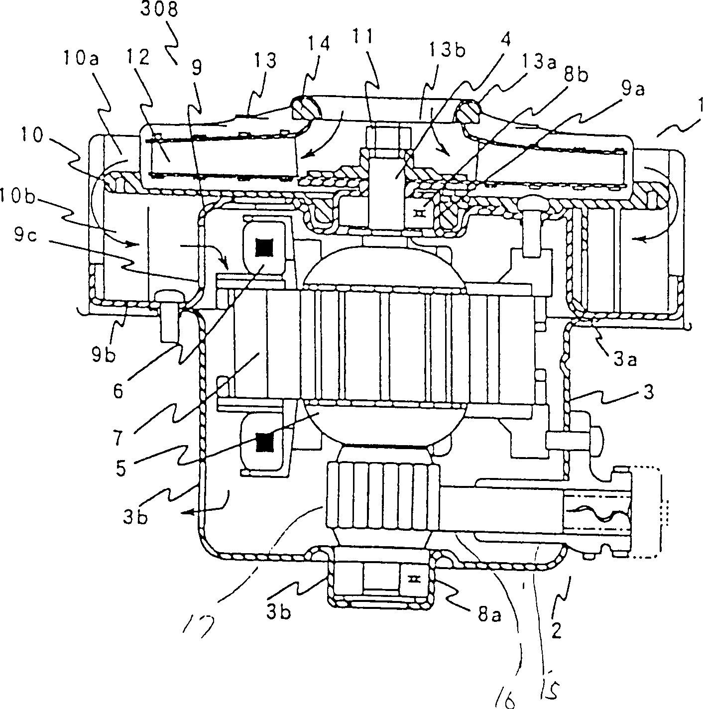
[0045] Figure 11 It shows a longitudinal sectional view of the electric vacu...


PUM


Abstract

The invention discloses an electric cleaner which has an air volume above 1.0 cubic meter per minute. The rotation number of the electric blower is arranged between the range from 40000 to 50000 rpm; area ratio of the co-adjacent hypothetic circle area of the front end of the blade center in the centrifugal impeller to the entrance area of the centrifugal impeller is arranged between 1.0 to 1.4; the dimension ratio of the blade external periphery outlet width to the external diameter is above 0.07; the sectional area ratio of the blade internal periphery flow route to the external one is blow 0.74; the dimension ratio of the blade inlet width to the outlet width is below 2.0; the ratio of the fillet curvature radius to the blade inlet width is from 0.6 to 0.9.

Description

technical field [0001] The present invention relates to electric vacuum cleaners, and particularly relates to reduction in size and weight and high output of an electric blower as a driving source of suction force thereof. Background technique [0002] Today's electric vacuum cleaners for general households are required to have a stronger suction force in order to meet market requirements such as carpet waste that is difficult to absorb. Suction power is used as the unit of suction force. In recent years, with this improvement in suction power, electric vacuum cleaners with motors of the 1000W class have been released. [0003] In electric vacuum cleaners, commutator-type motors are mainly used, and their aerodynamic characteristics are as follows: figure 2 shown. exist figure 2 In the aerodynamic characteristics of the electric vacuum cleaner, as the suction air volume on the horizontal axis decreases, the load on the commutator motor decreases, the current value, that ...

Claims


Application Information

Patent Timeline
Patent Type & Authority Patents(China)
IPC IPC(8): A47L5/12A47L5/22F04D29/30
CPCA47L9/0081A47L9/22H02K7/14Y10S416/00
Inventor 丰岛久则星忠行中居贵弘常乐文夫宫下邦夫小松茂三郎田原和雄安部岳志田岛泰治岩濑幸司佐藤繁则篠崎利也
Owner HITACHI LTD
Why Eureka
Try Eureka