Optical glass side-edge polishing device

A technology of polishing device and optical glass, which is applied in the direction of grinding driving device, grinding/polishing equipment, machine tool for surface polishing, etc., can solve the problems of inconvenient adjustment of position and angle of polishing device, etc.

Inactive Publication Date: 2020-02-21
SINOPOL ELECTRONICS TECH
View PDF0 Cites 0 Cited by
  • Summary
  • Abstract
  • Description
  • Claims
  • Application Information

AI Technical Summary

Problems solved by technology

[0003] The existing optical glass polishing device cannot adjust the angle, and the polishing device is inconvenient to adjust the position

Method used


Image

  • Optical glass side-edge polishing device
  • Optical glass side-edge polishing device
  • Optical glass side-edge polishing device

Examples


Embodiment Construction

[0018] The following will clearly and completely describe the technical solutions in the embodiments of the present invention with reference to the accompanying drawings in the embodiments of the present invention. Obviously, the described embodiments are only some, not all, embodiments of the present invention. Based on the embodiments of the present invention, all other embodiments obtained by persons of ordinary skill in the art without making creative efforts belong to the protection scope of the present invention.

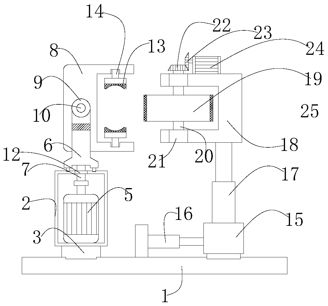
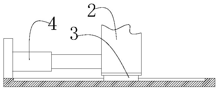
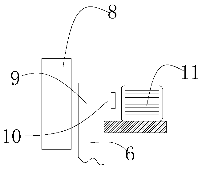
[0019] Such as Figure 1-3 As shown, the present invention provides a technical solution: a side polishing device for optical glass, comprising a base plate 1, a motor box 2 is provided on the left side of the upper surface of the base plate 1, and a slider 3 is fixedly connected to the bottom of the motor box 2. The bottom of the block 3 has a chute on the upper surface of the base plate 1, the slide block 3 is movably connected with the chute, the back side ...


PUM


Abstract

The invention relates to the technical field of optical glass processing, and discloses an optical glass side-edge polishing device. The optical glass side-edge polishing device comprises a bottom plate. A motor box is arranged on the left side of the upper surface of the bottom plate. A sliding block is fixedly connected to the bottom of the motor box. A sliding groove is formed in the position,located on the upper surface of the bottom plate, of the lower part of the sliding block, a motor I is fixedly connected to the bottom of the inner wall of the motor box, a movable rod is arranged onthe upper part of the motor box, a rotating shaft I is fixedly connected to the bottom of the movable rod, a bearing I is fixedly connected to the top of the motor box, the bottom of the rotating shaft I penetrates into the motor box and is movably connected with the bearing I, the bottom of the rotating shaft I is fixedly connected with the top of the motor I through a connecting rod and a coupling, and a clamping module is arranged on one side of the top of the movable rod. According to the optical glass side-edge polishing device, the clamping module is driven to rotate by a motor II, so that the angle of glass on the clamping module is adjusted at random, the motor box is pushed by a hydraulic push rod I at the bottom of the motor box, and the clamping module is driven to move forwardand backward.

Description

technical field [0001] The invention relates to the technical field of optical glass processing, in particular to an optical glass side polishing device. Background technique [0002] Glass that can change the direction of light propagation and change the relative spectral distribution of ultraviolet, visible or infrared light. Optical glass in the narrow sense refers to colorless optical glass; optical glass in the broad sense also includes colored optical glass, laser glass, quartz optical glass, anti-radiation glass, ultraviolet and infrared optical glass, fiber optic glass, acousto-optic glass, magneto-optical glass and photochromic Glass. Optical glass can be used to manufacture lenses, prisms, mirrors and windows in optical instruments. Components made of optical glass are key elements in optical instruments. [0003] The existing optical glass polishing device cannot adjust the angle, and the polishing device is inconvenient to adjust the position. Contents of th...

Claims


Application Information

Patent Timeline
Patent Type & Authority Applications(China)
IPC IPC(8): B24B9/14B24B29/02B24B41/06B24B47/12B24B41/02B24B47/22
CPCB24B9/14B24B9/146B24B29/02B24B41/02B24B41/06B24B47/12B24B47/22
Inventor 叶昊明陈永桥
Owner SINOPOL ELECTRONICS TECH
Why Eureka
Try Eureka