Grinding device for galvanized iron alloy door
A ferroalloy and shell technology, applied in grinding/polishing safety devices, grinding machines, grinding racks, etc., can solve problems such as difficult to control the grinding force, damage to galvanized ferroalloy doors, and easy splashing to users, etc., to improve protection effect, the effect of prolonging the service life
- Summary
- Abstract
- Description
- Claims
- Application Information
AI Technical Summary
Problems solved by technology
Method used
Image

Examples
Embodiment 1
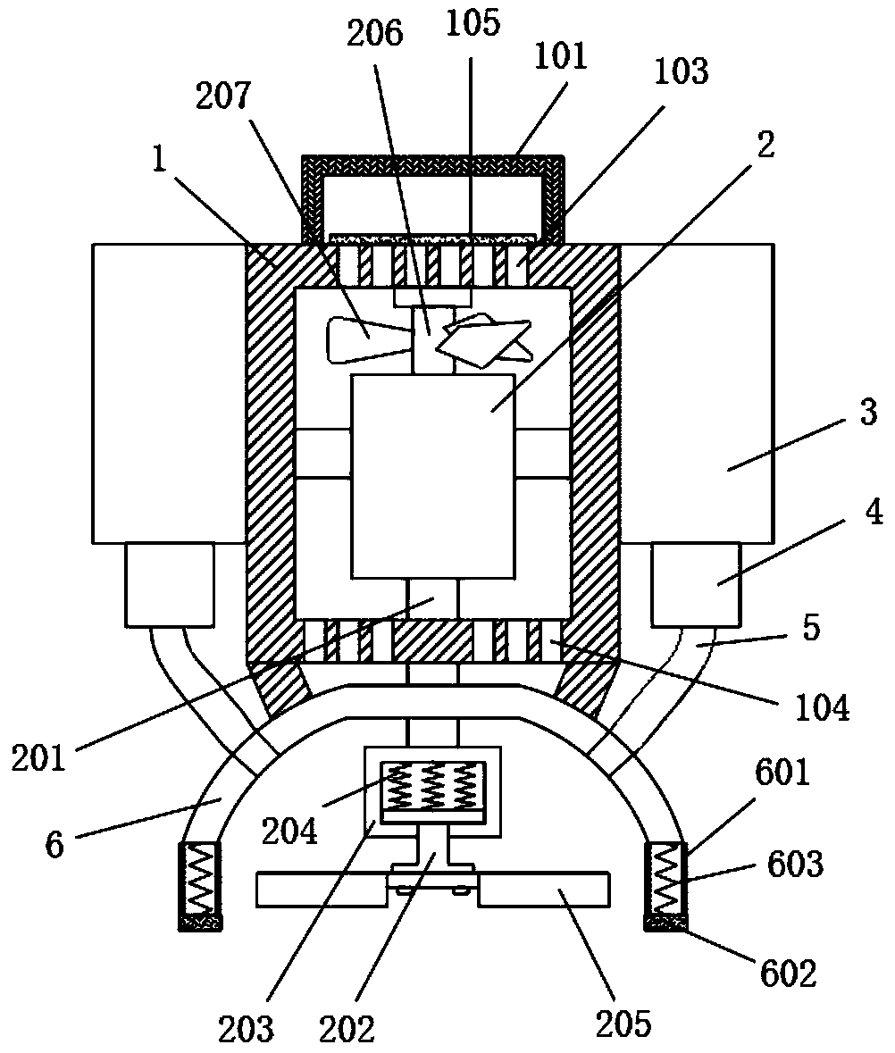
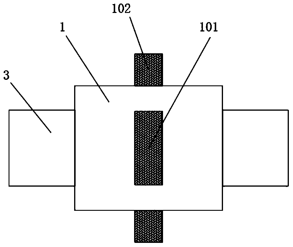
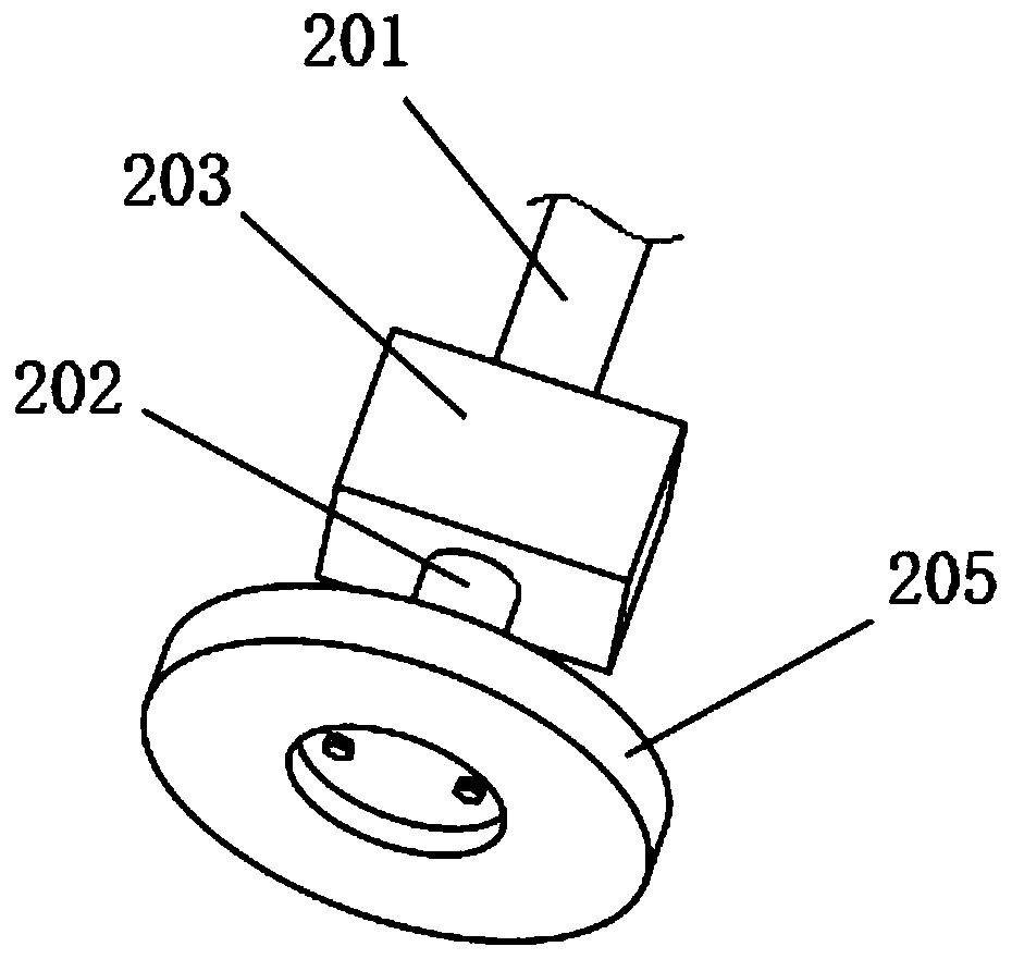
[0020] see Figure 1-3 , a grinding device for a galvanized iron alloy door, comprising a housing 1 and a grinding assembly mounted on the housing 1, a rear handle 101 is fixedly installed on the housing 1, the grinding assembly includes a rotating block 203 and a rotating shaft 202, and the rotating block 203 is provided with a cavity inside, the rotating shaft 202 is slidingly clamped in the cavity of the rotating block 203 and the rotating shaft 202 and the rotating block 203 are elastically connected by the first spring 204, and the rotating shaft 202 is fixedly equipped with a grinding disc 205, so A grinding motor 2 is fixedly installed inside the housing 1, and the first output shaft 201 of the grinding motor 2 is fixedly connected to the rotating block 203. In order to prevent debris generated during grinding from splashing on the user's eyes and causing damage to the user, the described A protective assembly is fixedly installed on the casing 1, and the protective ass...
Embodiment 2
[0027] This embodiment is a further improvement on the basis of Embodiment 1. Compared with Embodiment 1, the main difference is that: the housing 1 is evenly distributed with air inlets 103 and air outlets 104, and the grinding motor 2 The fan blade 207 is fixedly installed on the second output shaft 206 of the galvanized iron alloy door. The grinding motor 2 drives the fan blade 207 to rotate through the second output shaft 206 to dissipate heat from the grinding motor 2 while grinding the galvanized ferroalloy door. 2 service life.
[0028] In order to prevent dust outside the housing 1 from entering the housing 1 through the air inlet 103 , a dustproof net 105 is fixedly installed at the air inlet 103 on the housing 1 .
[0029] The working principle of this embodiment: the grinding motor 2 drives the fan blade 207 to rotate through the second output shaft 206 to dissipate heat from the grinding motor 2, prolong the service life of the grinding motor 2, and fix the dustpro...
PUM
 Abstract
Description
Claims
Application Information
 - Generate Ideas
- Intellectual Property
- Life Sciences
- Materials
- Tech Scout
- Unparalleled Data Quality
- Higher Quality Content
- 60% Fewer Hallucinations
Browse by: Latest US Patents, China's latest patents, Technical Efficacy Thesaurus, Application Domain, Technology Topic, Popular Technical Reports.
© 2025 PatSnap. All rights reserved.Legal|Privacy policy|Modern Slavery Act Transparency Statement|Sitemap|About US| Contact US: help@patsnap.com