3D printing device and 3D printing system
A 3D printing and outlet tube technology, applied in the field of 3D printing, can solve the problems of large size, difficult to obtain printed products, and inability to cut materials to be printed, and achieve the effect of high printing efficiency
- Summary
- Abstract
- Description
- Claims
- Application Information
AI Technical Summary
Problems solved by technology
Method used
Image
Examples
no. 1 example
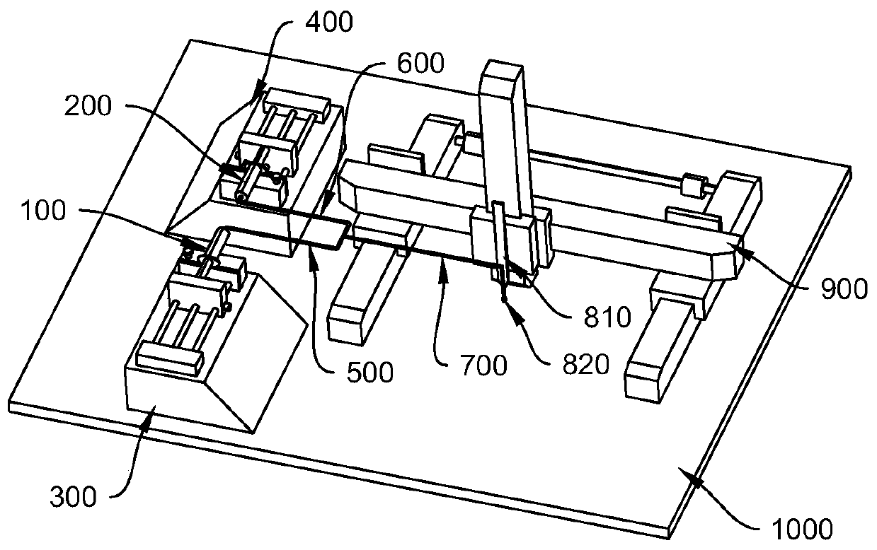
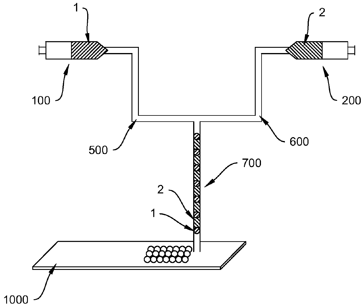
[0031] refer to figure 1 and figure 2 , respectively show a schematic view and a schematic view of the structure of the 3D printing device in the first embodiment, in which the structure is simplified and some components are omitted. The 3D printing device in this embodiment includes a first housing part 100, a second housing part 200, a first push-out part 300, a second push-out part 400, a first inlet pipe 500, a second inlet pipe 600, an outlet pipe 700, a heating part (including the preheating plate 810 and the heating tube 820 ), the displacement part 900 and the substrate 1000 and other components.
[0032] The first material 1 is loaded in the first container 100 , and the second material 2 is loaded in the second container 200 . The first material 1 and the second material 2 are materials to be printed that are different in hydrophilicity and hydrophobicity and are immiscible with each other, and they will not react with each other. The first receiving part 100 is ...
no. 2 example
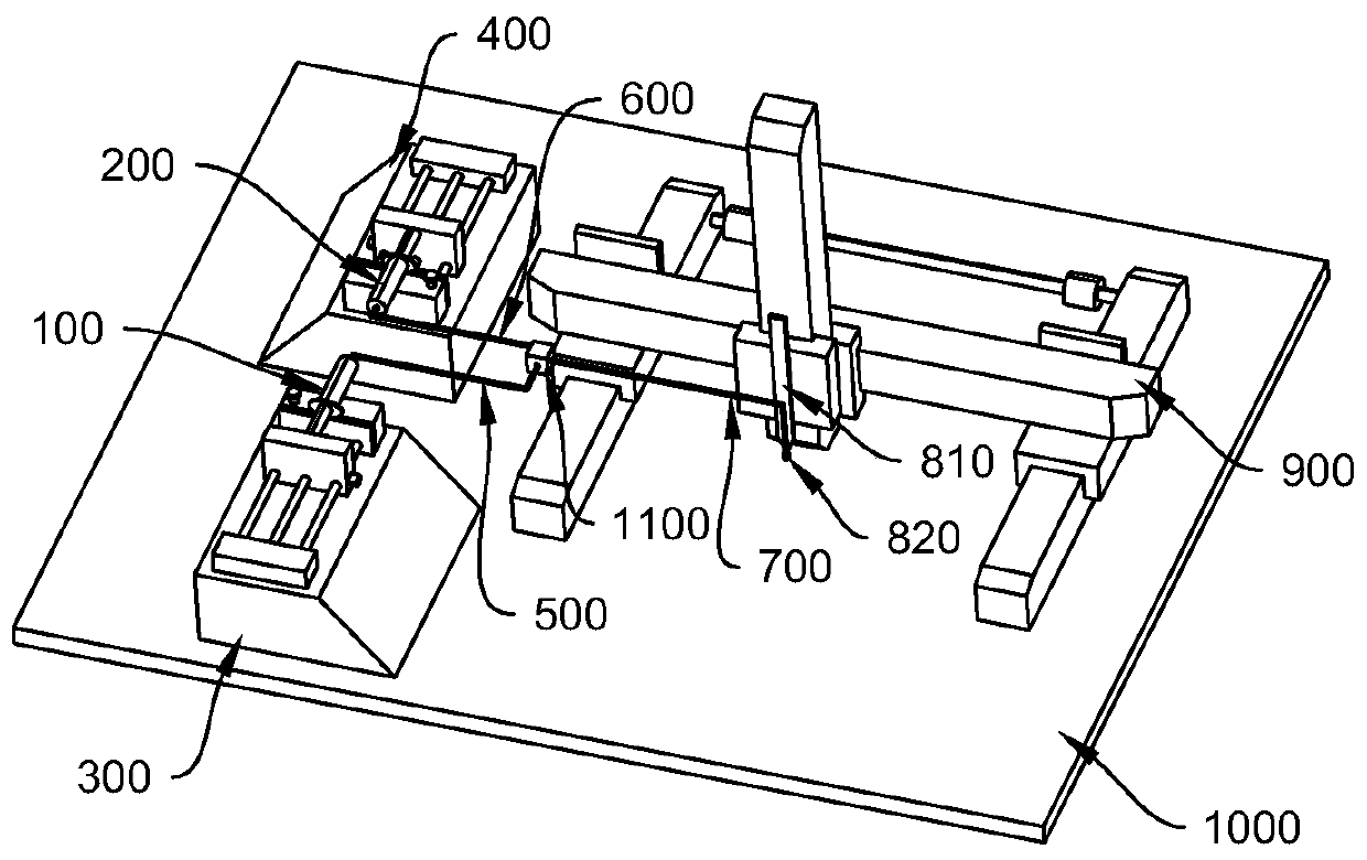
[0047] This embodiment is an alternative embodiment to the first embodiment. refer to image 3 and Figure 4 , respectively show a schematic view and a schematic view of the structure of the 3D printing device in the second embodiment, in which the structure is simplified and some components are omitted. In this embodiment, a PDMS three-way valve 1100 is added. The first inlet pipe 500 , the second inlet pipe 600 and the outlet pipe 700 are all connected to the PDMS three-way valve 1100 . By setting the PDMS three-way valve 1100, micro-flow control can be realized, and the parameters such as the size and flow rate of the microspheres can be finely adjusted to improve the printing precision and accuracy. Of course, ordinary valves can also be used, but ordinary valves cannot fine-tune the parameters.
[0048] In addition, the degree to which the three channels of the PDMS three-way valve 1100 are opened can also be adjusted to change the flow rate and size of the microspher...
no. 3 example
[0050] This embodiment is an alternative embodiment of the first embodiment. In this embodiment, the fluorine oil is placed in the second containing portion 200, which has a low boiling point and will not react with the materials in the first containing portion 100. The viscosity and hydrophobicity of the two are different. The heating temperature at the heating tube 820 is lower than the boiling point of the fluorine oil, and when the fluorine oil reaches the position of the heating tube 820, it will quickly volatilize into gas. This part of the gas will give extra thrust to the microspheres of the material to be printed, and accelerate the ejection speed of the microspheres. Of course, other materials other than fluorine oil can also be placed in the second accommodation part 200, as long as the viscosity is low, biologically inert (avoiding its reaction with the first material), low boiling point, easy to volatilize, non-toxic and harmless, and easy to degrade. Can.
[00...
PUM
 Abstract
Description
Claims
Application Information
 - R&D Engineer
- R&D Manager
- IP Professional
- Industry Leading Data Capabilities
- Powerful AI technology
- Patent DNA Extraction
Browse by: Latest US Patents, China's latest patents, Technical Efficacy Thesaurus, Application Domain, Technology Topic.
© 2024 PatSnap. All rights reserved.Legal|Privacy policy|Modern Slavery Act Transparency Statement|Sitemap


