
Stage flight case

A flight box and stage technology, applied in the field of stage flight boxes, can solve problems such as glue overflow and unsightly appearance, and achieve the effects of avoiding misalignment, firm connection, and accurate connection position

Pending Publication Date: 2020-02-21
广州鲁易箱包有限公司
View PDF0 Cites 0 Cited by
  • Summary
  • Abstract
  • Description
  • Claims
  • Application Information

AI Technical Summary

Problems solved by technology

Furthermore, in the above structure, the sealing ring is between the upper and lower aluminum frames in the vertical direction, and the sealant is connected to one of the aluminum frames by glue. In this way, if the glue is too little, the connection of the sealing ring is firm. If there is too much glue, the glue may overflow, resulting in an unattractive appearance

Method used


Image

  • Stage flight case
  • Stage flight case
  • Stage flight case

Examples


Embodiment 1

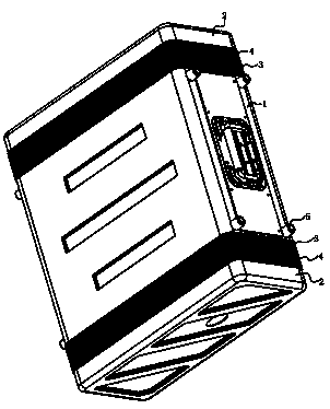
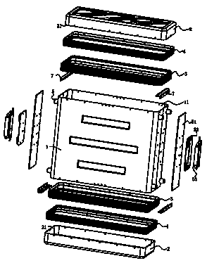
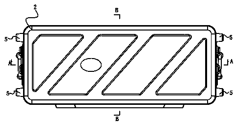
[0036] Such as Figure 1 to Figure 5 As shown, the stage flight box includes a box body 1, a box cover 2, a box side frame body 3, a cover side frame body 4 and a handle device.

[0037] Support feet 5 are provided on two opposite sides of the box body 1 , and the support feet 5 are used to support the box body 1 . The box body 1 has an opening edge 11, in this embodiment, withfigure 1 with figure 2 For the viewing angle direction, there are opening edges 11 at the upper and lower ends of the box body 1 respectively.

[0038] The lid 2 has an opening edge 21 .

[0039] Such as figure 2 , Image 6 , Figure 7 with Figure 8 As shown, the cross-section of the box-side frame body 3 includes a box-side connecting portion 31 and a first docking portion 32. The first docking portion 32 is connected to one end of the box-side connecting portion 31 and extends inward at the middle of the box-side connecting portion 31. The first flange 33, a slot 34 is formed between the firs...

Embodiment 2

[0049] Such as Figure 14 As shown, the difference between the present embodiment and embodiment 1 is that the pulley pull bar 9 is added, and other structures are all the same. The pulley pull rod 9 includes a pull rod seat 91 , a telescopic pull rod 92 , a pull rod fixing seat 93 and a roller 94 . Pull rod seat 91 is fixed on the casing, telescopic pull rod 92 is a double pull rod structure, and one end of telescopic pull rod 92 is fixed on the pull rod seat 91, and telescopic pull rod 92 is also fixed on the pull rod holder 93, like this, telescopic pull rod 92 and casing The connection is reliable, the tie rod holder 93 is fixed on the casing, and the two ends of the tie rod holder 91 are respectively equipped with rollers 94. In this way, there is no need to install rubber wheels on the box body, and the requirements for the molding of the box body are reduced. At the same time, it is convenient to carry the stage flight box by using the pull rod.


PUM


Abstract

The invention discloses a stage flight case. A case body and a case cover are included. A case side frame is arranged on the opening edge of the case body. A cover side frame is arranged on the opening edge of the case cover and connected with the case side frame. The cross section of the case side frame comprises a case side connecting part and a first butt joint part, and a first flange inwardsextending is arranged at the middle portion of the case side connecting part. A clamp groove is formed between the first flange and the first butt joint part. The cross section of the cover side framecomprises a cover side connecting part and a second butt joint part. A support is clamped in the clamp groove and comprises a support body and a bracket inwards bending and extending from one end ofthe support body. By utilization of the structure, connection of the case side frame and the case body is reliable and firm, connection of the case side frame and the case cover is reliable and firm,the size of the integral stage flight case becomes small, the space utilization rate is reduced, the transportation cost is reduced, and support connection is reliable and convenient.

Description

technical field [0001] The present invention relates to stage flight boxes. Background technique [0002] The stage air box is a new type of packaging product that replaces the transportation caused by the traditional simple wooden box packaging and transportation that cannot solve the disadvantages of stage lights and stage equipment not being effectively protected during long-distance transportation and poor mobility. [0003] The existing stage air box is mainly composed of a box body, a box cover and an aluminum frame. Aluminum frames are respectively arranged on the opening edges of the box body and the box cover, and the aluminum frame is connected with the box body and the box cover through a slot and a protrusion. , In this way, when the box body, box cover or aluminum frame is subjected to extrusion force, etc., the aluminum frame is easily separated from the box body or box cover. The structure of the aluminum frame is as follows: its cross section mainly includes...

Claims


Application Information

Patent Timeline
Patent Type & Authority Applications(China)
IPC IPC(8): B65D55/02B65D25/24B65D53/02B65D25/20B65D6/24B65D85/68
CPCB65D7/24B65D11/1866B65D25/20B65D25/24B65D53/02B65D55/02B65D85/68B65D2555/02
Inventor 赵建华
Owner 广州鲁易箱包有限公司
Learn More