Wire and cable winding device
A coiling device, wire and cable technology, which is applied in the directions of transportation and packaging, transportation of filamentous materials, and thin material handling, etc. The effect of efficiency
- Summary
- Abstract
- Description
- Claims
- Application Information
AI Technical Summary
Problems solved by technology
Method used
Image

Examples
Embodiment 1
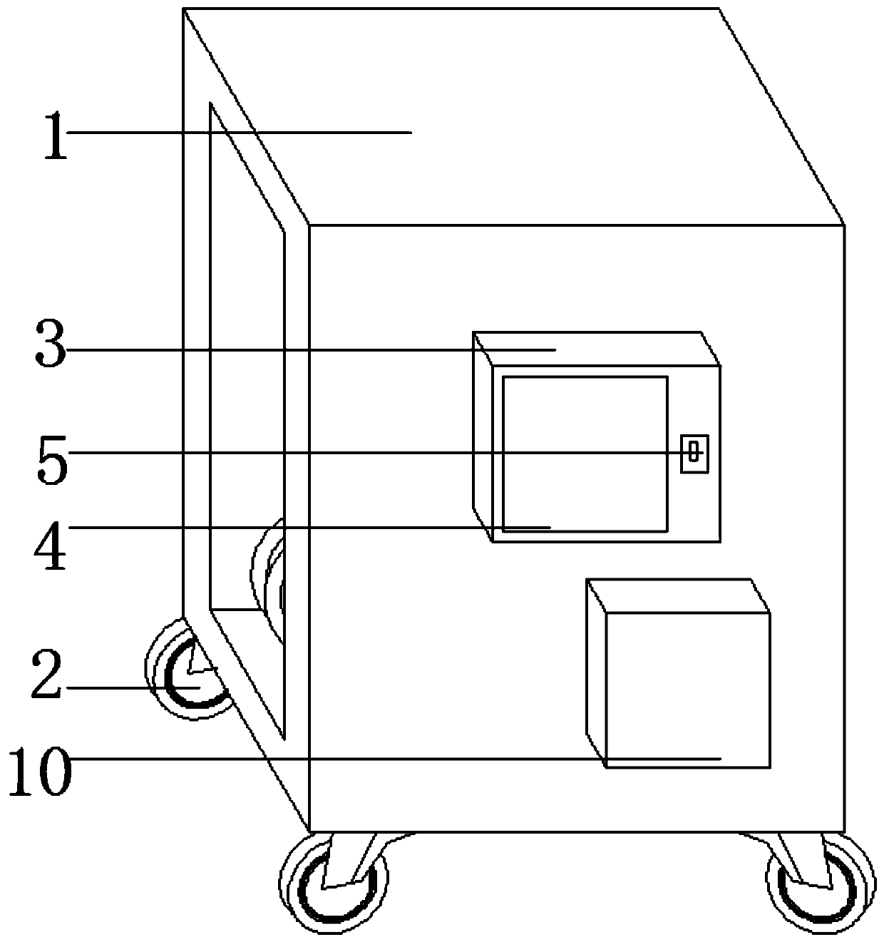
[0027] see figure 1 , 4 , a wire and cable coiling device, including a main body 1 and a control box 3, a control box 3 is arranged in the middle of the front of the main body 1, the control box 3 is fixed on the main body 1 by screws, a display 4 is embedded on the surface of the control box 3, and the right side of the display 4 There is a power switch 5 on the side, and the power switch 5 is fixed on the control box 3 by screws. The left side of the control box 3 is embedded with a power interface 7, and the right side of the power interface 7 is equipped with a controller 6. The controller 6 is fixed on the control box by screws. Inside the box 3, a voltage protector 8 is provided on the lower side of the controller 6, and the voltage protector 8 is fixed in the control box 3 by screws. The right side of the voltage protector 8 is glued with a battery 9, which is easy to operate through the touch display on the display. 9 Provide power support for the device;
Embodiment 2
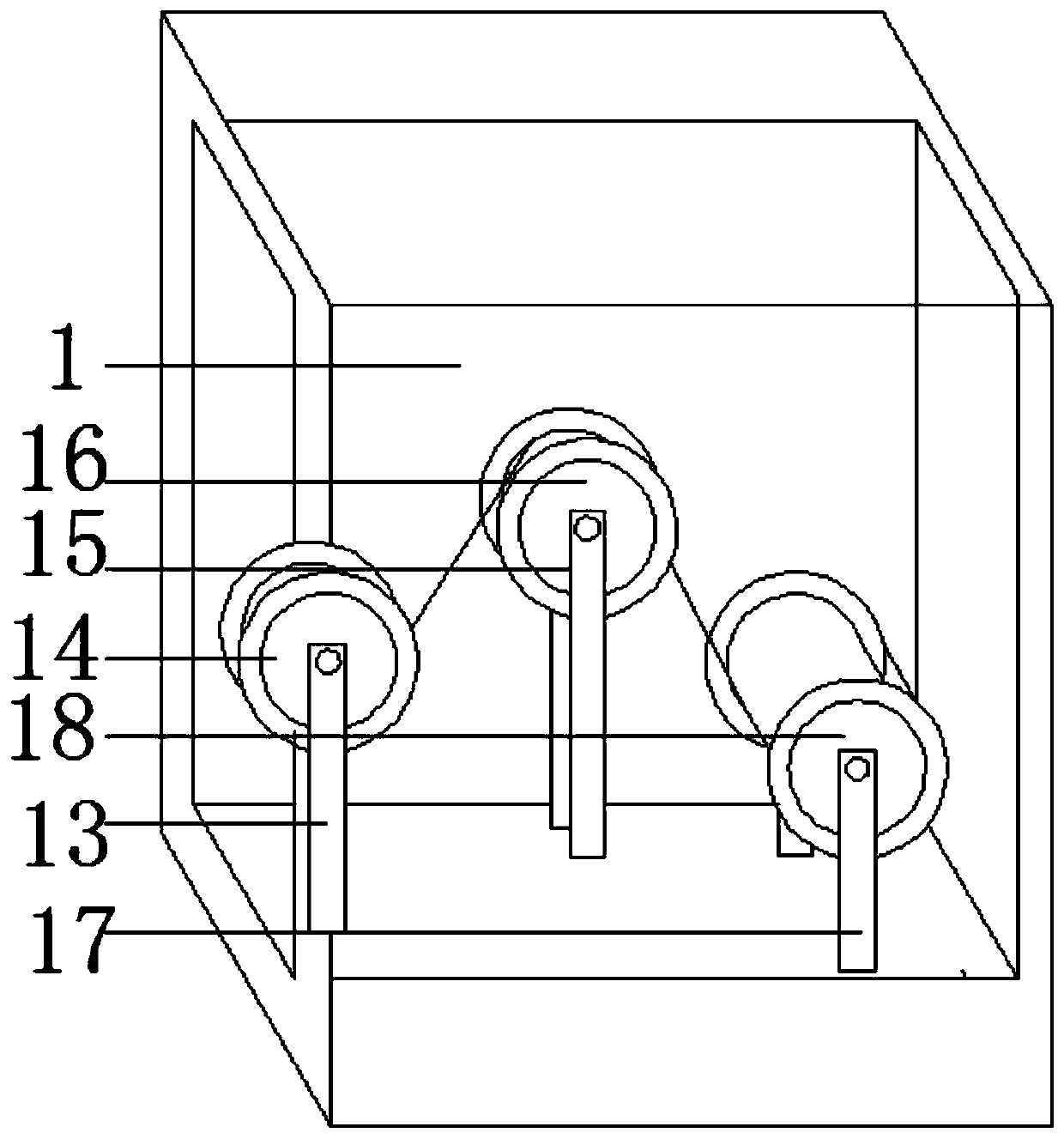
[0029] see figure 1 , 3 , a wire and cable coiling device; including a main body 1, a first support frame 13, a second support frame 15 and a third support frame 17, the left side of the main body 1 is provided with a first support frame 13, and the first support frame 13 is right There is a second support frame 15 on the side, and a third support frame 17 is provided on the right side of the second support frame 15. The first support frame 13, the second support frame 15 and the third support frame 17 are two front and rear corresponding installations on the main body. 1, a first alignment wheel 14 is provided between the first support frames 13, the front and rear ends of the first alignment wheel 14 are mounted on the first support frame 13 through bearings, and a second alignment wheel 14 is arranged between the second support frames 15. Two along the line wheel 16, the front and rear ends of the second line wheel 16 are all installed on the second support frame 15 by bea...
Embodiment 3
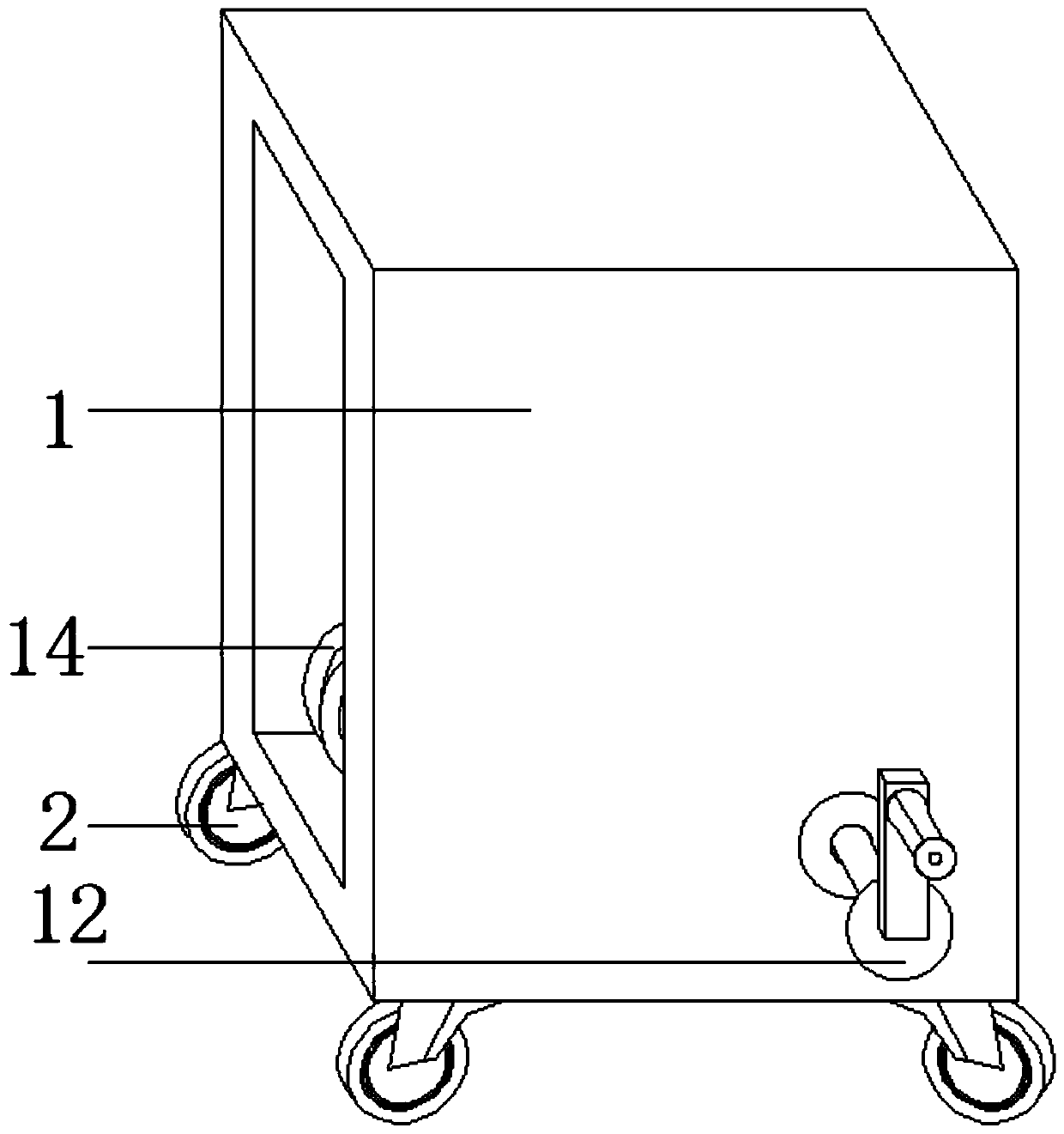
[0031] see Figure 1-5 , a wire and cable coiling device, including a main body 1, a driving box 10 is arranged at the bottom right of the control box 3, the driving box 10 is fixed on the main body 1 by screws, a driving motor 11 is installed in the driving box 10, and the rotating shaft of the driving motor 11 passes through Bearing and take-up wheel 18 rotating shafts are connected to provide power support for the operation of this device. The four corners of the bottom of the main body 1 are provided with uniform universal wheels 2, and the universal wheels 2 are all fixed on the main body 1 by screws to facilitate movement. The main body 1 is a cube, and The left and right sides are penetrating surfaces. The back of the main body 1 is provided with a hand handle 12 corresponding to the position of the take-up wheel 18. The hand handle 12 is connected to the take-up wheel 18 through a bearing. The hand handle 12 provides manual operation power. The display 4 adopts a touch ...
PUM
 Abstract
Description
Claims
Application Information
 - R&D
- Intellectual Property
- Life Sciences
- Materials
- Tech Scout
- Unparalleled Data Quality
- Higher Quality Content
- 60% Fewer Hallucinations
Browse by: Latest US Patents, China's latest patents, Technical Efficacy Thesaurus, Application Domain, Technology Topic, Popular Technical Reports.
© 2025 PatSnap. All rights reserved.Legal|Privacy policy|Modern Slavery Act Transparency Statement|Sitemap|About US| Contact US: help@patsnap.com