Series diaphragm pump with non-return and anti-seepage functions

A technology of anti-leakage and diaphragm pumps, which is applied to pumps with flexible working elements, parts of pumping devices for elastic fluids, pumps, etc., which can solve the problem of poor ability of umbrella valves to pass foreign matter and easy adsorption of umbrella valves Particles, diaphragm pump can not work and other problems, to achieve the effect of high tablet loading efficiency, improved water pumping efficiency, and simple structure

Active Publication Date: 2020-02-21
XIAMEN CONJOIN ELECTRONICS TECH
View PDF9 Cites 13 Cited by
  • Summary
  • Abstract
  • Description
  • Claims
  • Application Information

AI Technical Summary

Problems solved by technology

[0005] (1): The existing diaphragm pump itself does not have a check system, and a single check valve needs to be connected externally, which results in large volume, high cost and low assembly efficiency
[0006] (2): The existing diaphragm pump uses 2 umbrella valves and 1 diaphragm as the water inlet and outlet system. The umbrella valve is easy to stick, which may cause the opening pressure of the pump to be too high or the umbrella valve cannot be opened; and the umbrella valve The ability to pass foreign matter is poor. In the actual use process, foreign matter particles of various sizes will be mixed in the water. When the water pump passes through the water, the umbrella valve is easy to absorb particles, causing the inlet and outlet to be blocked, so that the diaphragm pump cannot work.

Method used


Image

  • Series diaphragm pump with non-return and anti-seepage functions
  • Series diaphragm pump with non-return and anti-seepage functions
  • Series diaphragm pump with non-return and anti-seepage functions

Examples


no. 1 example

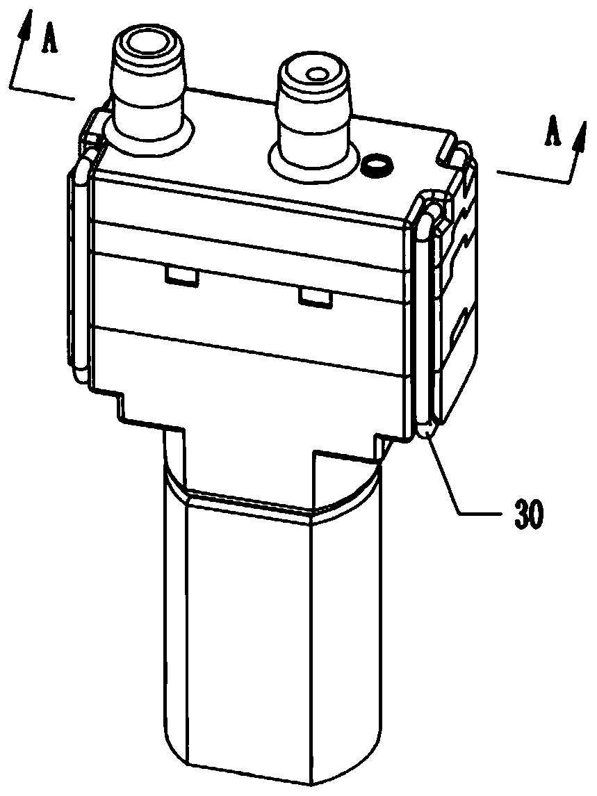
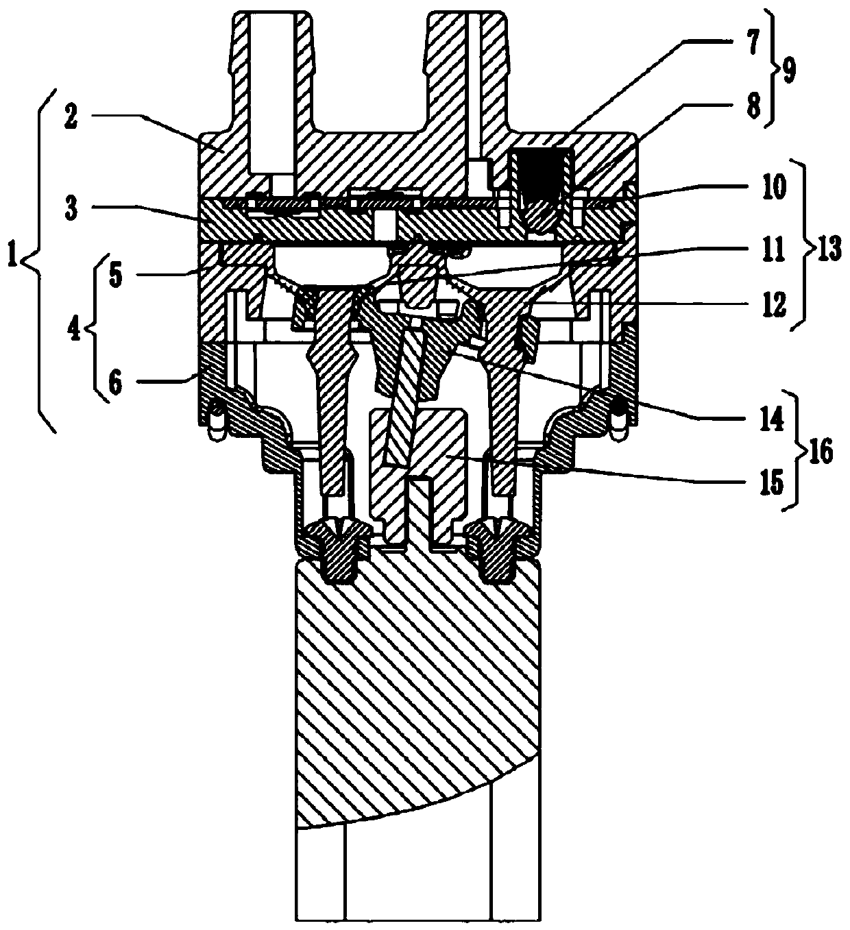
[0044] Depend on figure 1 , figure 2 and image 3 As shown, in this embodiment, a series diaphragm pump with check and anti-leakage functions includes:

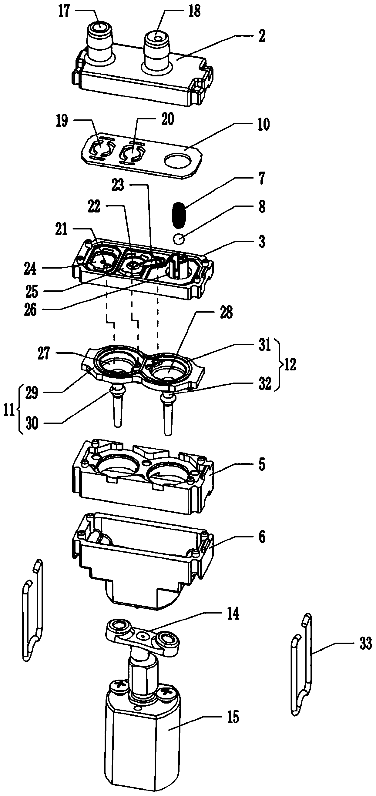
[0045] The housing mechanism 1 includes a support assembly 4, a diaphragm seat 3 supported on the support assembly 4, and an upper cover 2 supported on the diaphragm seat 3 and provided with an inlet channel 17 and an outlet channel 18; the upper cover 2 and the diaphragm seat 3 sandwich the first chamber 24, the second chamber 25 and the third chamber 26, the liquid inlet channel 17 can be connected with the first chamber 24, and the liquid outlet channel 18 can be connected with the third chamber 26 The diaphragm seat 3 is provided with a first passage 21 communicating with the first chamber 24, and a second passage 22 and a third passage 23 communicating with the second chamber 25 respectively;

[0046] Diaphragm mechanism 13, which includes the diaphragm 10 sandwiched between the upper cover 2 and the diaphragm seat 3...

no. 2 example

[0063] Depend on Figure 6 As shown, in this embodiment, the anti-return mechanism 9 also includes a non-return ball 8 and a return spring 7 . Specifically, the upper cover 2 is provided with a movable groove 37 that is compatible with the return spring 7 and the check ball 8 , and the return spring 7 is located in the movable groove 37 . When the second movable capsule 12 moves upward, the solution in the second capsule cavity 28 pushes away the check ball 8 , allowing the check ball 8 to move upward and compress the return spring 7 . When the second movable bag 12 moves downward, the return spring 7 will drive the check ball 8 to move downward to seal the first opening 34 . Wherein, the movable groove 37 can play the role of positioning the return spring 7 . At the same time, compared with the first embodiment, the movable groove 37 of this case is a groove placed upside down on the upper cover 2, which will not accumulate foreign matter, and has a stronger ability to pass...


PUM


Abstract

The invention discloses a series diaphragm pump with non-return and anti-leakage functions, and relates to the technical field of diaphragm pumps. The diaphragm pump comprises a shell mechanism, a diaphragm mechanism, a driving mechanism and a non-return mechanism; specifically, the shell mechanism comprises a supporting component, a diaphragm seat and an upper cover, wherein a first accommodatingcavity, a second accommodating cavity and a third accommodating cavity are clamped between the upper cover and the diaphragm seat, and the diaphragm seat is provided with a first channel, a second channel and a third channel; the diaphragm mechanism comprises a diaphragm, and a first movable bag and a second movable bag which are connected in series, wherein the diaphragm is provided with a firstdiaphragm body and a second diaphragm body, the first movable bag comprises a first bag cavity, the second movable bag is provided with a second bag cavity, the first channel and the second channel communicate with the first bog cavity, and the third channel and the third cavity communicate with the second bag cavity; the driving mechanism is used for driving the first movable bag and the secondmovable bag to move up and down in a staggered mode; and the non-return mechanism is used for preventing external solution from flowing back to the second bag cavity.

Description

technical field [0001] The invention relates to the technical field of diaphragm pumps, in particular to a serial diaphragm pump with check and anti-leakage functions. Background technique [0002] Diaphragm liquid pumps provide circular motion by the motor, and then the diaphragm in the liquid pump is reciprocated by a mechanical device, thereby compressing and stretching the air in the pump cavity. There is a pressure difference between the water inlet and the external atmospheric pressure. Under the action of the pressure difference, water is pressed into the water inlet and then discharged from the water outlet. This diaphragm liquid pump has been well applied in occasions such as small household appliances and medical equipment. [0003] An existing diaphragm pump consisting of a motor, an eccentric wheel, a steel needle, a curved rod, a lower seat, a bell seat, a bell, a middle plate, an umbrella, a diaphragm, an upper cover, and a circlip; , drives the eccentric whe...

Claims


Application Information

Patent Timeline
Patent Type & Authority Applications(China)
IPC IPC(8): F04B43/04F04B53/10F04B53/00F04B23/04
CPCF04B43/04F04B53/10F04B53/00F04B23/04F04B43/028F04B53/1002
Inventor 颜宏
Owner XIAMEN CONJOIN ELECTRONICS TECH
Why Eureka
Try Eureka