Cooling fan and electronic equipment

A heat dissipation fan and air outlet technology, which is applied to mechanical equipment, parts of pumping devices for elastic fluids, non-variable pumps, etc., can solve the problems of affecting system performance, high R&D costs, large manpower consumption, cost and Time and other issues, to achieve the effect of reducing noise, low noise, and solving the unbalanced flow

Pending Publication Date: 2020-02-21
HEFEI LCFC INFORMATION TECH
View PDF0 Cites 0 Cited by
  • Summary
  • Abstract
  • Description
  • Claims
  • Application Information

AI Technical Summary

Problems solved by technology

[0003] However, the way to control the size of the air inlet of the cooling fan requires repeated tests in the design process to optimize the fan noise, which consumes a lot of manpower, cost and time in the research and development process
And blocking the air inlet will affect the heat dissipation performance of the fan
The method of reducing the fan speed will significantly reduce the flow of air, and there is a risk of affecting system performance
The way to optimize the design of the blade shape must pass repeated trial production verification, the development time is long, and the research and development cost is relatively high

Method used


Image

  • Cooling fan and electronic equipment
  • Cooling fan and electronic equipment
  • Cooling fan and electronic equipment

Examples


Embodiment Construction

[0022] In order to enable those skilled in the art to better understand the technical solutions of the embodiments of the present invention, the present invention will be described in detail below in conjunction with the accompanying drawings and specific implementation methods.

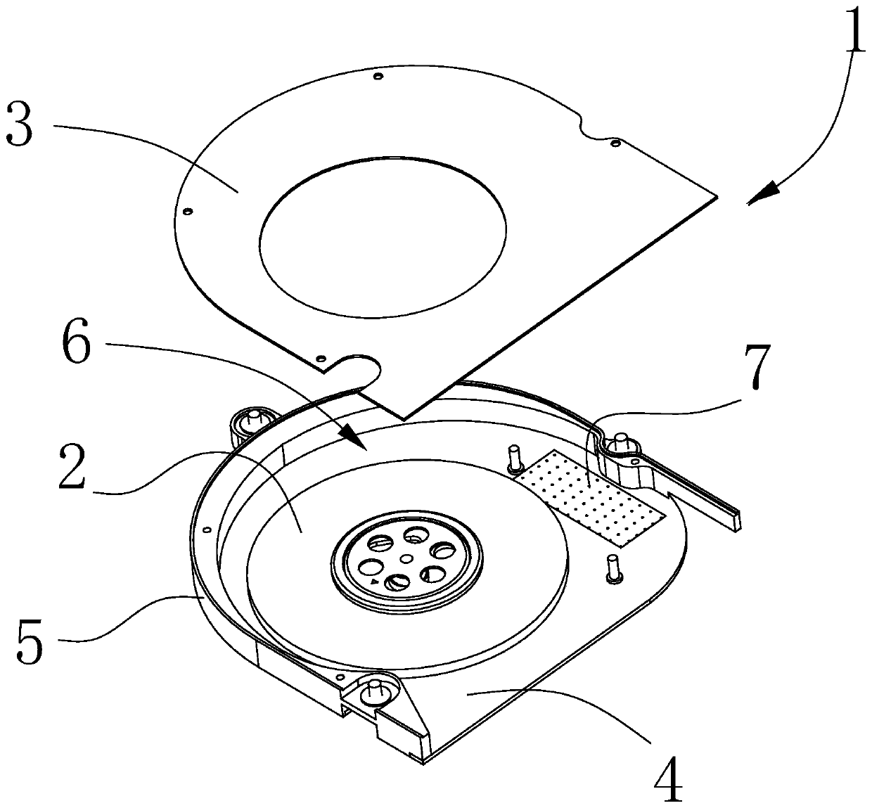
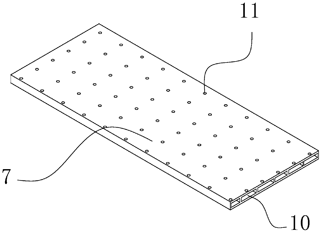
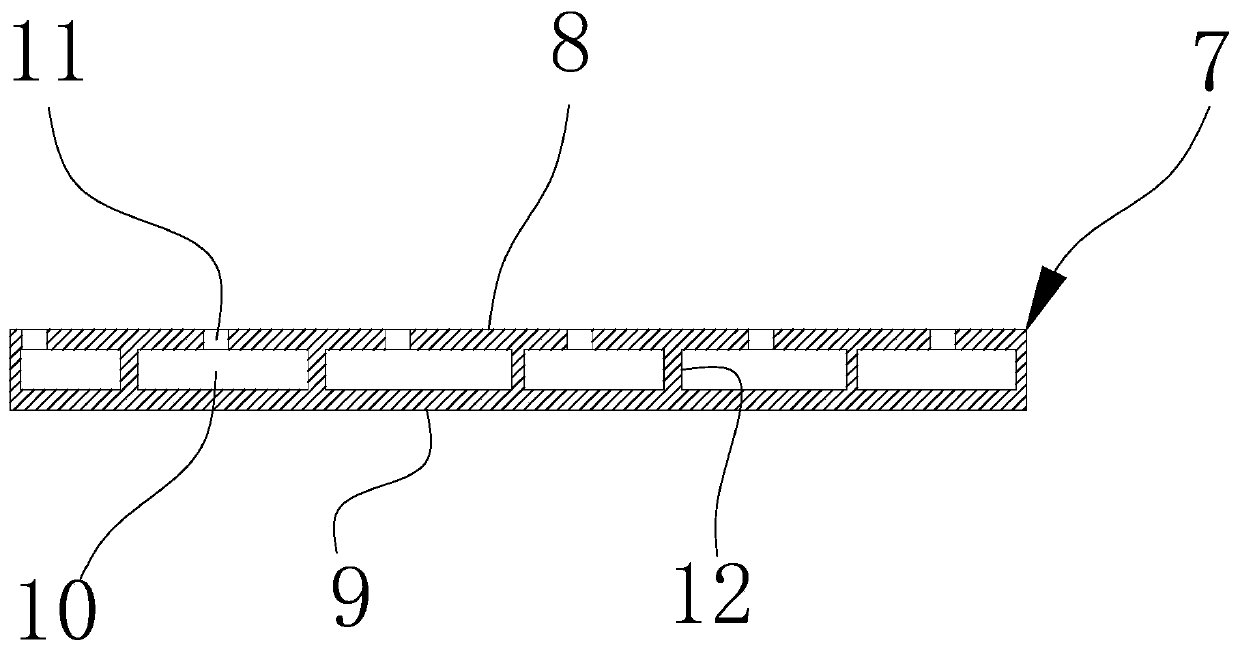
[0023] figure 1 It is a schematic diagram of the three-dimensional structure of the cooling fan according to the embodiment of the present invention, see figure 1 As shown, the cooling fan of the embodiment of the present invention includes: a casing 1 and an impeller 2, and the casing 1 includes a top plate 3 and a bottom plate 4 oppositely arranged, and a side plate enclosed between the top plate 3 and the bottom plate 4 5. The top plate 3, the bottom plate 4 and the side plate 5 enclose the inner cavity 6 of the housing 1, the impeller 2 is arranged in the inner cavity 6, the top plate 3 and the bottom plate All or part of at least one of 4 is made of a sound-absorbing board 7; the sound-absorbin...


PUM


Abstract

The embodiment of the invention provides a cooling fan and electronic equipment. The cooling fan comprises a shell body, wherein the shell body comprises a top plate and a bottom plate which are oppositely arranged, and a side plate arranged between the top plate and the bottom plate in a surrounding mode, the top plate, the bottom plate and the side plate surround and form an inner cavity of theshell body, an impeller is arranged in the inner cavity, and all or part of at least one of the top plate and the bottom plate is composed of a sound absorption plate; and the sound absorption plate comprises a first plate body and a second plate body which are oppositely arranged, a plurality of silencing cavities which are arranged at intervals are arranged between the first plate body and the second plate body, the first plate body is close to the inner cavity, and a plurality of through holes communicating with the silencing cavities are formed in the first plate body. According to the cooling fan, through a sound absorption structure formed by the through holes and the silencing cavities on the sound absorption plate, noise can be effectively absorbed, the noise of the cooling fan canbe remarkably reduced, an air inlet and an air outlet of the cooling fan do not need to be shielded, and the problem that the noise and flows cannot be balanced can be solved.

Description

technical field [0001] Embodiments of the present invention relate to the technical field of electronic equipment, and in particular, relate to a cooling fan and electronic equipment. Background technique [0002] There is a problem of heat generation in the operation of electronic equipment, and cooling fans are usually used to dissipate heat, but noise will be generated during the operation of the cooling fan. In order to make the noise of the cooling fan meet the standard, in the prior art, the size of the air inlet of the cooling fan is usually controlled , reduce the fan speed, and optimize the design of the blade shape to reduce noise. [0003] However, the design process of controlling the size of the air inlet of the cooling fan requires repeated tests to optimize the fan noise, which consumes a lot of manpower, cost and time in the research and development process. And blocking the air inlet will affect the cooling performance of the fan. The method of reducing th...

Claims


Application Information

Patent Timeline
Patent Type & Authority Applications(China)
IPC IPC(8): F04D25/08F04D29/44F04D29/66
CPCF04D25/08F04D29/441F04D29/663
Inventor 王瑜评刘家俊林承纬
Owner HEFEI LCFC INFORMATION TECH
Why Eureka
Try Eureka