Supercharge Your Innovation With Domain-Expert AI Agents!

Helium flame-retardant sealing structure for liquid rocket engine turbopump

A liquid rocket and sealing structure technology, applied in liquid fuel engines, rocket engine devices, machines/engines, etc., can solve problems such as explosion, oxidant and fuel contact combustion, to avoid contact combustion, safe and reliable isolation, and improve surface hardness and the effect of friction resistance

Active Publication Date: 2020-02-21
BEIJING AEROSPACE PROPULSION INST
View PDF6 Cites 2 Cited by
  • Summary
  • Abstract
  • Description
  • Claims
  • Application Information

AI Technical Summary

Problems solved by technology

However, the sealing sleeve and the rotating shaft are in a clearance fit, and oxidizer and fuel also exist in the fit gap, which will cause destructive failures such as oxidant and fuel contact combustion or even explosion

Method used


Image

  • Helium flame-retardant sealing structure for liquid rocket engine turbopump
  • Helium flame-retardant sealing structure for liquid rocket engine turbopump
  • Helium flame-retardant sealing structure for liquid rocket engine turbopump

Examples


Embodiment 1

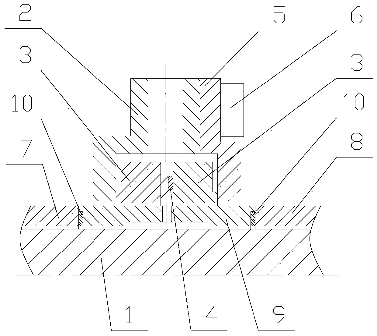
[0028] A liquid rocket engine turbopump helium flame-retardant sealing structure, including a rotating shaft 1, a sealing shell 2, a floating ring 3, a wave spring 4, a cover plate 5, a first bushing 7, a second bushing 8, and a sealing bushing 9. Aluminum pad10.

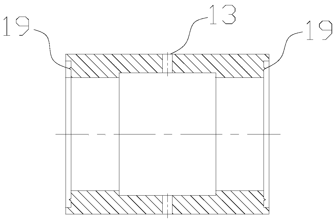
[0029] The first shaft sleeve 7, the sealing shaft sleeve 9, and the second shaft sleeve 8 are sequentially set on the rotating shaft 1, and the sealing shaft sleeve 9 is sealed and connected with the first shaft sleeve 7 and the second shaft sleeve 8; the sealing The shaft sleeve 9 is provided with an annular groove on the surface close to the rotating shaft 1. When the sealing sleeve 9 is set on the rotating shaft 1, an annular cavity 14 is formed between the annular groove and the rotating shaft 1; The annular groove is provided with 4-6 radial holes in total, and the 4-6 radial holes 13 are distributed along the circumference of the sealing sleeve 9 .

[0030] The sealing housing 2 is sleeved on the sealing sha...

Embodiment 2

[0034] A liquid rocket engine turbopump helium flame-retardant sealing structure, including a rotating shaft 1, a sealing shell 2, a floating ring 3, a wave spring 4, a cover plate 5, a screw 6, a first bushing 7, a second bushing 8, a seal Shaft sleeve 9, aluminum pad 10; Wherein floating ring 3 has two roads, as figure 1 shown.

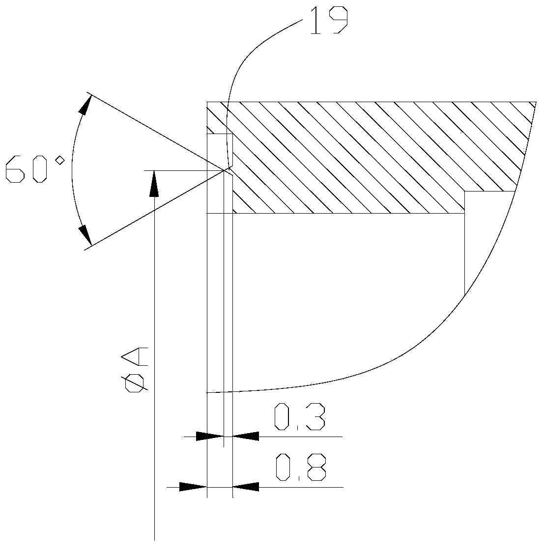
[0035] Four radial holes 13 are arranged in the middle position of the floating ring 3 corresponding to the back-to-back installation of the sealing sleeve 9, and sealing teeth 19 are arranged at both ends of the sealing sleeve 9, such as Figure 2~3 shown. The inner surface of the sealing shaft sleeve 9 is processed with an annular groove. After assembly, the sealing sleeve 9 forms an annular cavity 14 with the rotating shaft 1 . When working, the helium in the dynamic seal isolation cavity 12 enters the annular cavity 14 from the middle gap of the floating ring 3 through the radial hole 13 of the seal sleeve 9 to form a helium isolation cavity ...


PUM

PropertyMeasurementUnit
Diameteraaaaaaaaaa
Cone angleaaaaaaaaaa
Heightaaaaaaaaaa

Abstract

The invention provides a helium flame-retardant sealing structure for a liquid rocket engine turbopump, and belongs to the technical field of rocket engines. The helium flame-retardant sealing structure comprises a rotary shaft 1, a seal housing 2, a floating ring 3, a wave spring 4, a cover plate 5, a first shaft sleeve 7, a second shaft sleeve 8 and a seal shaft sleeve 9, wherein the first shaftsleeve 7, the seal shaft sleeve 9 and the second shaft sleeve 8 sleeve the rotary shaft 1 in sequence; an annular groove is formed in the surface, close to the rotary shaft 1, of the seal shaft sleeve 9, and an annular cavity 14 is formed between the annular groove and the rotary shaft 1; a radial hole 13 is formed in the portion, at the position of the annular groove, of the seal shaft sleeve 9;the seal housing 2 sleeves the seal shaft sleeve 9, and a helium inlet 11 and an isolation cavity 12 which communicate with each other are formed in the seal housing 2; after the cover plate 5 is connected with the seal housing 2, the floating ring 3 is located in the isolation cavity 12; and the wave spring 4 is used for applying axial preload to the floating ring 3, and making the isolation cavity 12 separated from the radial hole 13. By means of the helium flame-retardant sealing structure, isolation of an oxidizing agent from a fuel is achieved, and the safety of the turbopump is greatlyimproved.

Description

technical field [0001] The invention relates to a helium flame-retardant sealing structure of a liquid rocket engine turbo pump, which belongs to the technical field of rocket engines. Background technique [0002] When oxidant and fuel exist in the turbopump of liquid rocket engine, the contact combustion of the two media is a typical catastrophic failure, which is extremely harmful. Once the oxidant comes into contact with the fuel, it will develop fission combustion, causing turbine blade ablation, casing burn-through, and even the entire engine explosion. Therefore, it is necessary to completely isolate the oxidizer and fuel when the turbo pump is working. At present, turbopumps often use dynamic seals in the form of floating rings or labyrinth seals, and a certain pressure of helium is introduced into the middle of the floating ring or labyrinth seal to isolate the oxidant and fuel in the chambers on both sides. Usually, a sealing sleeve is installed on the rotating s...

Claims


Application Information

Patent Timeline
IPC IPC(8): F04D29/10F02K9/46
CPCF02K9/46F04D29/106
Inventor 沈文金黄克松蒋文山崔垒柴皓李小芬刘恒金志磊林奇燕叶小强
Owner BEIJING AEROSPACE PROPULSION INST
Features
  • R&D
  • Intellectual Property
  • Life Sciences
  • Materials
  • Tech Scout
  • Unparalleled Data Quality
  • Higher Quality Content
  • 60% Fewer Hallucinations
Learn More